Nanometer light guide plate, method for preparing nanometer light guide plate and display device

A nano-light guide plate and light guide plate technology, applied in the field of light guide plates, can solve the problems that the finished product cannot be cut at will, the production cost increases, and the equipment is complicated, etc., and achieve the effects of promoting and applying, enhancing applicability, and high light conversion rate

Inactive Publication Date: 2021-04-02
凯盛科技股份有限公司
View PDF12 Cites 0 Cited by
  • Summary
  • Abstract
  • Description
  • Claims
  • Application Information

AI Technical Summary

Problems solved by technology

[0003] The light guide plates widely used at present are mainly prepared by injection molding, photolithography, laser engraving or printing. Among them, the equipment used in the injection molding method is complicated, the price is high, and the production cost increases; the light guide plate made by photolithography The surface roughness is not good, and the loss of light energy is relatively large; although the laser engraving method can accurately control the depth of the scattering structure, the efficiency is very low, which is not convenient for mass production; the light guide plate made by the printing method cannot be cut at will. There are application defects
At present, the thinnest thickness of the light guide plate produced is 2mm. The larger the size, the thickness must be increased accordingly in order to ensure the brightness, and the light guide effect is correspondingly poor. The thickest light guide plate does not exceed 20mm. Sometimes it is often difficult to meet the needs of the market, and its structure and preparation method need to be further improved

Method used


Image

  • Nanometer light guide plate, method for preparing nanometer light guide plate and display device
  • Nanometer light guide plate, method for preparing nanometer light guide plate and display device
  • Nanometer light guide plate, method for preparing nanometer light guide plate and display device

Examples


specific Embodiment 1

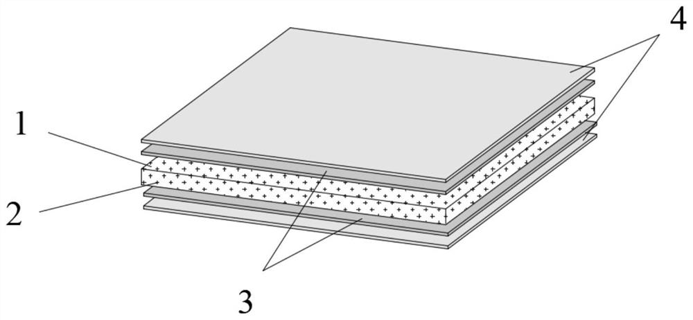
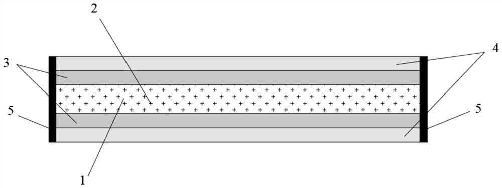
[0027] A nano light guide plate, comprising a light guide plate body 1 with a thickness of 0.8mm, the base material of the light guide plate body 1 is polycarbonate, and uniformly dispersed nano light scattering particles 2 are doped in the light guide plate body 1, and also Including nano-dispersed slurry and antioxidant, the upper surface and the lower surface of the light guide plate body 1 are respectively provided with a nano-reflection enhancement layer 3 with a thickness of 30 μm, and the side of the nano-reflection enhancement layer 3 away from the light guide plate body 1 is provided with a thickness of The protective layer 4 is 50 μm. In this embodiment, the nano-light scattering particles 2 are nano-silicon dioxide with a particle size of 20 nm, the nano-reflection enhancement layer 3 is a transparent material, and the protective layer 4 is pure PET plastic. 1 is surrounded by sidewalls 5, and the sidewalls 5 cover the nano-reflection enhancement layer 3 and the prot...

specific Embodiment 2

[0034] A nano light guide plate, comprising a light guide plate body 1 with a thickness of 10 mm, the base material of the light guide plate body 1 is polystyrene, uniformly dispersed nano light scattering particles 2 are doped in the light guide plate body 1, and it also includes The nano-dispersed slurry and the antioxidant are provided with a nano-reflection enhancement layer 3 with a thickness of 60 μm on the upper surface and the lower surface of the light guide plate body 1, and a thickness of 60 μm is provided on the side of the nano-reflection enhancement layer 3 away from the light guide plate body 1. The protective layer 4 is 120 μm. In this embodiment, the nano-light scattering particles 2 are nano-alumina with a particle size of 300 nm, the nano-reflection enhancing layer 3 is a transparent material, and the protective layer 4 is pure PET plastic. There are sidewalls 5 all around, and the sidewalls 5 cover the nano-reflection enhancement layer 3 and the protective l...

specific Embodiment 3

[0041]A nano light guide plate, comprising a light guide plate body 1 with a thickness of 5 mm, the base material of the light guide plate body 1 is polymethyl methacrylate, and uniformly dispersed nano light scattering particles 2 are doped in the light guide plate body 1, It also includes nano-dispersed slurry and antioxidant, and a nano-reflection enhancement layer 3 with a thickness of 50 μm is respectively provided on the upper surface and the lower surface of the light guide plate body 1, and the nano-reflection enhancement layer 3 is provided on the side away from the light guide plate body 1. There is a protective layer 4 with a thickness of 100 μm. In this embodiment, the nano-light scattering particles 2 are nano-titanium dioxide with a particle size of 100 nm, the nano-reflection enhancement layer 3 is a transparent material, and the protective layer 4 is pure PET plastic. 1 is surrounded by sidewalls 5, and the sidewalls 5 cover the nano-reflection enhancement layer...


PUM

PropertyMeasurementUnit
particle diameteraaaaaaaaaa
thicknessaaaaaaaaaa
thicknessaaaaaaaaaa

Abstract

The invention relates to the technical field of light guide plates, in particular to a nanometer light guide plate, which comprises a light guide plate body, uniformly dispersed nanometer light scattering particles are doped in the light guide plate body, and nanometer dispersion slurry and an antioxidant are further arranged in the light guide plate body, wherein the upper surface and the lower surface of the light guide plate body are respectively provided with a nanometer reflection enhancement layer, and one side of each nanometer reflection enhancement layer, which is far away from the light guide plate body, is provided with a protective layer, and the invention also provides a method for preparing the nanometer light guide plate and a display device. The nanometer light guide plateis high in light conversion rate, uniform in light, safe and environmentally friendly; the product can be cut into required sizes at will and is suitable for indoor and outdoor use, and the applicability of the product is enhanced; the surface is precise, double-sided light guiding is achieved, products with small thickness can be used under the condition of the same brightness, and cost is saved;any point light source and line light source can be used for area light source conversion, the process is simple, manufacturing is convenient, and application and popularization are facilitated.

Description

technical field [0001] The invention relates to the technical field of light guide plates, in particular to a nano light guide plate, a method for preparing a nano light guide plate and a display device. Background technique [0002] The light guide plate is made of optical-grade acrylic or PC board. It uses high-tech materials with a very high refractive index and does not absorb light. Laser engraving and V-shaped cross grids are used on the bottom of the optical-grade plate. Engraving, UV screen printing and other technologies are used to print the light guide points, and use the optical grade plate to absorb the light emitted from the lamp to stay on the surface of the optical grade plate. When the light hits each light guide point, the reflected light will spread to all angles , and then destroy the reflection condition and emit from the front of the light guide plate. Through light guide points of various densities and sizes, the light guide plate can be made to emit ...

Claims


Application Information

Patent Timeline
Patent Type & Authority Applications(China)
IPC IPC(8): G02B6/00
CPCG02B6/0051G02B6/0055G02B6/0093G02B6/0065
Inventor 樊黎虎杨金发许波钟汝梅周道钧年睿峰罗丹黄涛涛
Owner 凯盛科技股份有限公司
Why Eureka
Try Eureka