Cutting fluid filtering device for numerically-controlled machine tool

A technology of numerical control machine tools and filter devices, which is applied in the field of numerical control machine tools, can solve the problems of inconvenient disassembly of filter devices, poor filtration performance, waste of cutting fluid raw materials, etc., and achieve the effects of easy disassembly, cleaning or replacement, increased stability, and good filter performance

Inactive Publication Date: 2021-04-06
胡玮
View PDF9 Cites 2 Cited by
  • Summary
  • Abstract
  • Description
  • Claims
  • Application Information

AI Technical Summary

Problems solved by technology

[0004] The purpose of the present invention is to provide a cutting fluid filter device for CNC machine tools, which has the advantages of good filtration performance and recyclable use, and solves the problem that the existing cutting fluid filter devices for CNC machine tools have poor filtration performance and cannot be recycled, which will cause cutting problems. The waste of liquid raw materials increases the production cost and cannot meet the needs of users. At the same time, it is not convenient to disassemble the filter device, which affects the filtering effect in the later stage and reduces the practicality of the cutting fluid filter device.

Method used

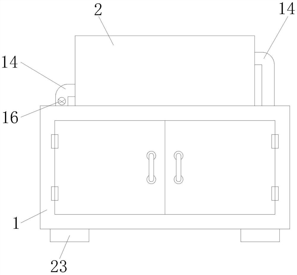
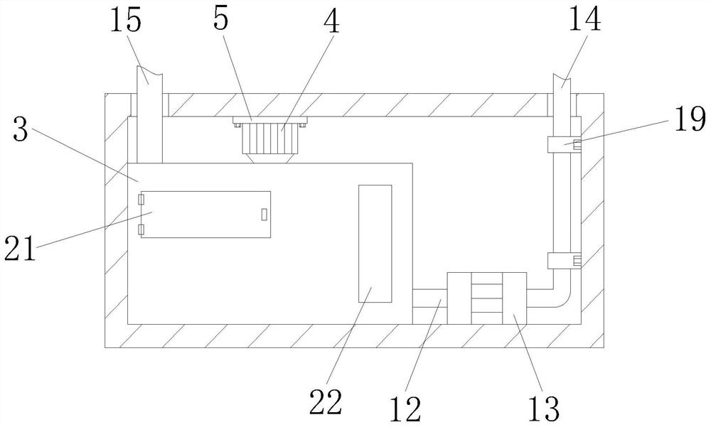
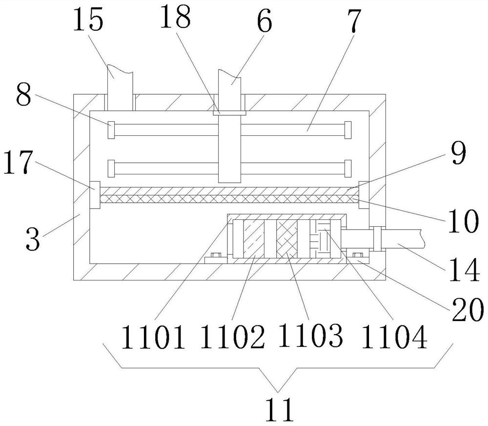

Image

  • Cutting fluid filtering device for numerically-controlled machine tool
  • Cutting fluid filtering device for numerically-controlled machine tool
  • Cutting fluid filtering device for numerically-controlled machine tool

Examples


Embodiment Construction

[0019] In order to enable those skilled in the art to better understand the technical solution of the present invention, the present invention will be described in detail below in conjunction with the accompanying drawings. The description in this part is only exemplary and explanatory, and should not have any limiting effect on the protection scope of the present invention. .

[0020] It should be noted that like numerals and letters denote similar items in the following figures, therefore, once an item is defined in one figure, it does not require further definition and explanation in subsequent figures.

[0021] It should be noted that the orientation or positional relationship indicated by the terms "center", "upper", "lower", "left", "right", "vertical", "horizontal", "inner" and "outer" are Based on the orientation or positional relationship shown in the drawings, or the orientation or positional relationship that the inventive product is usually placed in use, it is onl...


PUM


Abstract

The invention relates to a cutting fluid filtering device for numerically-controlled machine tool, which comprises a box body, an equipment main body is arranged at the top of the box body, a filtering box is arranged on the left side of the bottom of an inner cavity of the box body, a motor is arranged at the top of the filtering box, and a rotating shaft is fixedly connected to the output end of the motor. Through the arrangement of the box body, the equipment main body, the filter box, the motor, a mounting plate, the rotating shaft, a stirring paddle, a magnetic adsorption block, an adsorption filter plate, a filter screen, a filter assembly, a liquid suction pipe, a liquid suction pump, a liquid outlet pipe, a liquid discharge pipe, an electromagnetic valve and a mounting base, the advantages of good filtering performance and recyclability are achieved; the cutting fluid filtering device for the numerical control machine tool solves the problems that an existing cutting fluid filtering device for the numerical control machine tool is poor in filtering performance and cannot be recycled, cutting fluid raw materials are wasted, the production cost is increased, the requirements of users cannot be met, meanwhile, the filtering device is inconvenient to disassemble, the later-period filtering effect is affected, and the practicability of the cutting fluid filtering device is reduced.

Description

technical field [0001] The invention relates to the technical field of numerical control machine tools, in particular to a cutting fluid filtering device for numerical control machine tools. Background technique [0002] Cutting fluid is an industrial liquid used in metal cutting and grinding to cool and lubricate cutting tools and workpieces. Cooling performance, lubricating performance, anti-rust performance, degreasing and cleaning function, anti-corrosion function, and easy-to-dilute features, overcome the problems of traditional soap-based emulsions that are easy to smell in summer, difficult to dilute in winter, and poor anti-rust effect, and have no adverse effects on lathe paint It is suitable for the cutting and grinding of ferrous metals and is currently the most advanced grinding product. [0003] At present, the existing cutting fluid filter devices for CNC machine tools have poor filtration performance and cannot be recycled, which will cause waste of cutting f...

Claims


Application Information

Patent Timeline
Patent Type & Authority Applications(China)
IPC IPC(8): B01D36/00C10M175/00
CPCB01D36/00C10M175/00
Inventor 胡玮
Owner 胡玮
Why Eureka
Try Eureka