Flying wing layout wide-speed-domain pneumatic operation stability characteristic structure

A technology of layout and flying wings, applied in the directions of wings, wing adjustment, aircraft parts, etc., can solve the problems of low rudder efficiency, increased longitudinal stability, small force arm, etc., to reduce supersonic shock resistance, increase Equivalent sweep angle, the effect of improving take-off and landing performance

Inactive Publication Date: 2021-04-06
XIAN AIRCRAFT DESIGN INST OF AVIATION IND OF CHINA
View PDF3 Cites 2 Cited by
  • Summary
  • Abstract
  • Description
  • Claims
  • Application Information

AI Technical Summary

Problems solved by technology

[0010] In terms of control and stability characteristics, flying wing layout aircraft lacks a heading stabilizer, and the heading is generally statically unstable. During subsonic flight, it can be overcome by rudder surface augmentation control, but during supersonic cruise flight, the airflow disturbance caused by the deflection of the control surface cannot penetrate. The sonic surface cannot be forwarded, and the efficiency of the rudder surface is low. Controlling the attitude of the aircraft through the deflection of the rudder surface requires a larger deflection angle, which may complicate the flow of the wing surface, induce a strong shock wave, and bring a large drag increase
Secondly, due to the change of pressure distribution in the state of supersonic cruise, the aerodynamic focus will move backward, resulting in increased longitudinal stability. The rudder surface of the flying wing layout can only be arranged on the trailing edge of the wing, and the force arm is extremely small, so supersonic control is more difficult.

Method used


Image

  • Flying wing layout wide-speed-domain pneumatic operation stability characteristic structure
  • Flying wing layout wide-speed-domain pneumatic operation stability characteristic structure
  • Flying wing layout wide-speed-domain pneumatic operation stability characteristic structure

Examples


Embodiment Construction

[0033] This part is the embodiment of the present invention, which is used to explain and illustrate the technical solution of the present invention.

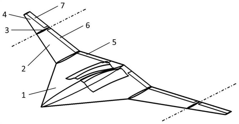
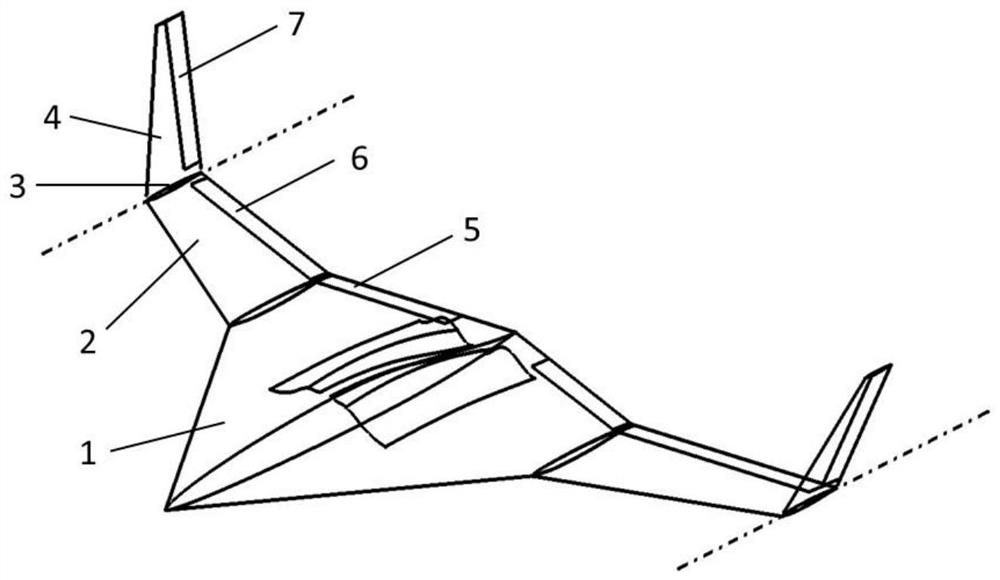
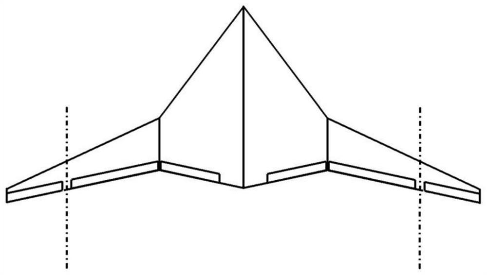
[0034] An aerodynamic stability structure with flying wing layout and wide speed range. The wing body is integrated with the fuselage of the flying wing layout. The double wings of the fuselage adopt a double-sweep layout. 1 is the wing section integrated with the fuselage, the inner wing section 1 has a large leading edge sweep angle, and the outer wing section has a small leading edge sweep angle; the outer wing section is also divided into an outer wing section fixed section 2 and an outer wing section that can be folded Section 4, the fixed section 2 of the outer wing section is fixedly connected with the inner wing section 1, the foldable section 4 of the outer wing section is dynamically connected with the fixed section 2 of the outer wing section through the rotating shaft 3 of the outer wing section, and the foldable secti...


PUM


Abstract

The invention belongs to the technical field of aviation aircraft design, and discloses a flying wing layout wide-speed-range aerodynamic operation stability characteristic structure, a wing body and flying wing layout integrated aircraft body, double wings of the aircraft body adopt double sweepback layout, the wings are divided into inner wing sections and outer wing sections, the inner wing sections are wing sections fused with the aircraft body, and the sweepback angles of the front edges of the inner wing sections are large; the sweepback angle of the front edge of the outer wing section is small; the outer wing section is further divided into an outer wing section fixing section and an outer wing section foldable section, the outer wing section fixing section is fixedly connected with the inner wing section, the outer wing section foldable section is in shaft driving connection with the outer wing section fixing section through an outer wing section rotating shaft, and the outer wing section foldable section rotates relative to the outer wing section rotating shaft so as to be folded upwards. When the structure is applied, different aerodynamic and operation stability performance requirements of low-speed take-off and landing, high subsonic speed cruise and supersonic speed cruise design points can be considered.

Description

technical field [0001] The invention belongs to the technical field of aviation vehicle design, and relates to a structure of a flying wing layout, in particular to an aerodynamic stability characteristic structure of a flying wing layout in a wide speed range. Background technique [0002] Compared with the traditional layout, the flying wing layout cancels the fuselage, horizontal tail, vertical tail and other components of the traditional layout aircraft, and the aerodynamic shape is closer to a pair of clean wings, which brings the following advantages in terms of structure, aerodynamics, and stealth : [0003] (1) High aerodynamic efficiency: The flying wing layout UAV cancels the horizontal tail and vertical tail in the conventional layout, effectively reducing the wetted area of ​​the whole machine, thereby reducing surface frictional resistance; effectively eliminating the mutual interference between components, Reduce interference resistance. At the same time, the...

Claims


Application Information

Patent Timeline
Patent Type & Authority Applications(China)
IPC IPC(8): B64C3/10B64C3/54B64C3/40
CPCB64C3/10B64C3/546B64C3/40
Inventor 周桢尧冯文梁
Owner XIAN AIRCRAFT DESIGN INST OF AVIATION IND OF CHINA
Why Eureka
Try Eureka