Long-stroke pumping unit installed at wellhead and underground sealing device

A technology of sealing device and pumping unit, which is applied in the direction of sealing/isolation, wellbore/well components, and production fluid, etc., which can solve the problems of wellhead sealing material leakage, increase of loss speed, and impact on production, and achieve good sealing effect, Ease of application, reduced wear and aging effects

Inactive Publication Date: 2021-04-06
大庆拓维石油科技开发有限公司
View PDF7 Cites 0 Cited by
  • Summary
  • Abstract
  • Description
  • Claims
  • Application Information

AI Technical Summary

Problems solved by technology

[0003] At present, conventional pumping units use wellhead packing to seal the polished rod, but long-stroke pumping units use wire rope winding for oil production. The polished rod of the sucker rod is the outer surface of the steel wire rope wrapped with nylon or resin to form a coating layer on the outer surface of the steel wire rope , so that it forms a flexible sucker rod with a smooth surface and becomes a polished rod shape for sealing. When the pumping unit reciprocates oil pumping, the steel wire rope coating layer is always in a state o

Method used


Image

  • Long-stroke pumping unit installed at wellhead and underground sealing device

Examples


Embodiment 1

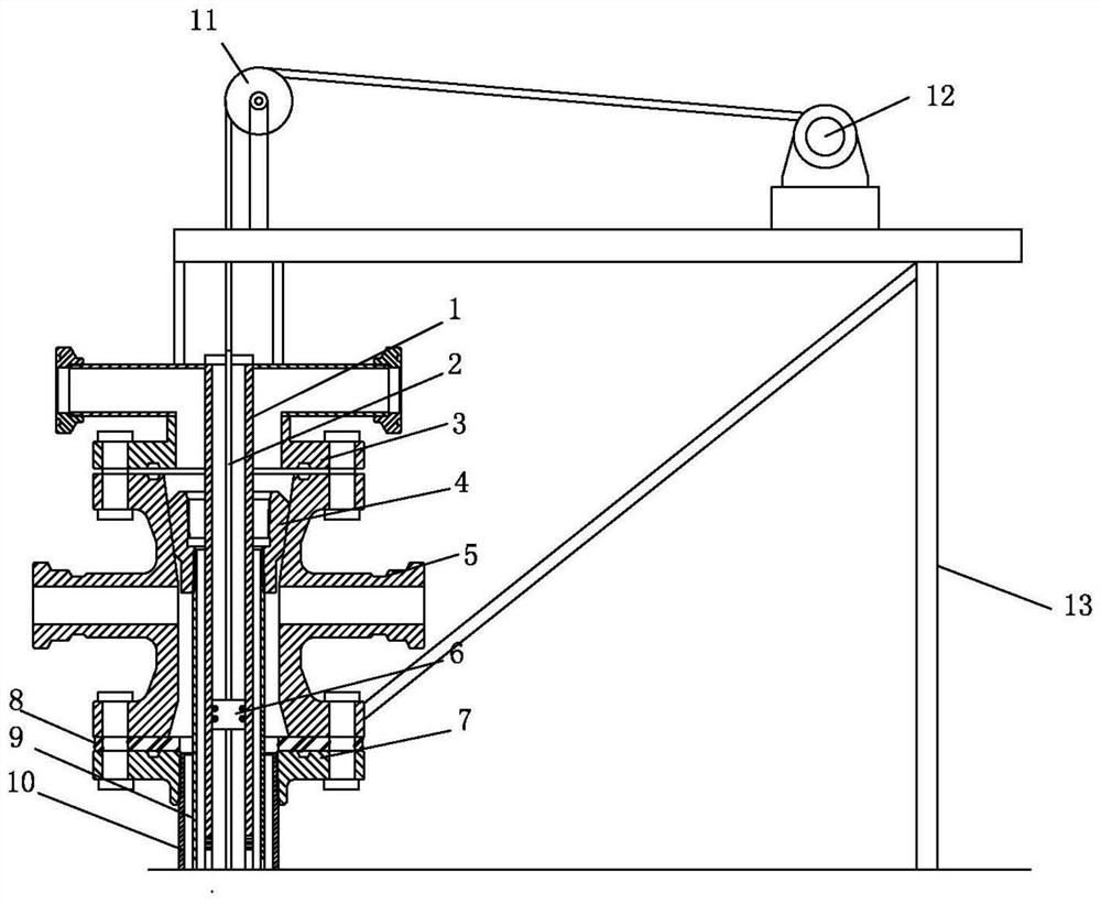
[0022] This embodiment provides a specific structure of a long-stroke pumping unit installed at the wellhead and a downhole sealing device, such as figure 1 As shown, it includes the large cross 5 and the bracket 13 installed on the equipment base 8, the middle part of the large cross 5 is interspersed with a sealing working cylinder 1, and the sealing sliding piston 6 is installed inside the sealing working cylinder 1, and the sealing sliding piston 6 A steel wire rope 2 is interspersed on the top.

[0023] The bracket 13 has an inverted L-shaped structure. A pulley assembly 11 and a long-stroke pumping unit 12 are installed above the horizontal end of the bracket 13. The pulley assembly 11 is located above the sealed working cylinder 1. One end of the wire rope 2 goes around the pulley assembly 11 and enters the long-stroke pumping unit. The interior of the stroke pumping unit 12.

[0024] The top of the big four-way 5 is also equipped with an oil well sealing device 3.

...

Embodiment 2

[0031] This embodiment provides a specific structure of a long-stroke pumping unit installed at the wellhead and a downhole sealing device, such as figure 1 As shown, it includes the large cross 5 and the bracket 13 installed on the equipment base 8, the middle part of the large cross 5 is interspersed with a sealing working cylinder 1, and the sealing sliding piston 6 is installed inside the sealing working cylinder 1, and the sealing sliding piston 6 A steel wire rope 2 is interspersed and installed on the top;

[0032] The bracket 13 has an inverted L-shaped structure. A pulley assembly 11 and a long-stroke pumping unit 12 are installed above the horizontal end of the bracket 13. The pulley assembly 11 is located above the sealed working cylinder 1. One end of the wire rope 2 goes around the pulley assembly 11 and enters the long-stroke pumping unit. The interior of the stroke pumping unit 12.

[0033] The top of the big four-way 5 is also equipped with an oil well sealing...


PUM


Abstract

The invention discloses a long-stroke pumping unit installed at a wellhead and an underground sealing device. The long-stroke pumping unit comprises a large four-way joint and a support which are installed on an equipment base, wherein a sealing working barrel is arranged in the middle of the large four-way joint in a penetrating mode, a sealing sliding piston is installed in the sealing working barrel, and a steel wire rope is installed on the sealing sliding piston in a penetrating mode; and the support is of an inverted-L-shaped structure, a pulley assembly and the long-stroke pumping unit are installed above the horizontal end of the support, the pulley assembly is located above the sealing working barrel, and one end of the steel wire rope winds around the pulley assembly and enters the long-stroke pumping unit. The long-stroke pumping unit is suitable for wellhead sealing of the long-stroke pumping unit, the wellhead sealing device is arranged below the wellhead, the sealing requirement of the ultra-long-stroke steel wire rope can be met, and abrasion and aging caused by traditional wellhead sealing are reduced; a movable sealing piston adopts a mode of combining soft sealing and hard sealing, and the sealing effect is good.

Description

technical field [0001] The invention relates to the technical field of wellhead sealing of long-stroke pumping units, in particular to a long-stroke pumping unit installed at the wellhead and a downhole sealing device. Background technique [0002] The long-stroke pumping unit has been vigorously developed because of its advantages of energy saving, high efficiency, long stroke and low stroke times, and it is suitable for deep wells and heavy oil wells. [0003] At present, conventional pumping units use wellhead packing to seal the polished rod, but long-stroke pumping units use wire rope winding for oil production. The polished rod of the sucker rod is the outer surface of the steel wire rope wrapped with nylon or resin to form a coating layer on the outer surface of the steel wire rope. , so that the flexible sucker rod with a smooth surface is formed into a polished rod shape for sealing. When the pumping unit reciprocates oil pumping, the steel wire rope coating layer a...

Claims


Application Information

Patent Timeline
IPC IPC(8): E21B33/03E21B33/10E21B43/00
CPCE21B33/03E21B33/10E21B43/121
Inventor 梅东辉
Owner 大庆拓维石油科技开发有限公司
Why Eureka
Try Eureka