Modeling method for simulating low-speed cutting process of fiber reinforced composite material

A composite material and modeling method technology, which is applied in the field of finite element model modeling for low-speed cutting process simulation of fiber-reinforced composite materials, can solve problems such as interlayer damage, fiber monofilament and matrix damage in macroscopic simulation methods, and achieve The effect of high practical significance and guiding value, reducing the number of experiments and reducing time cost

Active Publication Date: 2021-04-06
TIANJIN UNIVERSITY OF TECHNOLOGY
View PDF7 Cites 1 Cited by
  • Summary
  • Abstract
  • Description
  • Claims
  • Application Information

AI Technical Summary

Problems solved by technology

Due to the difference in the weaving structure of composite materials, there is a big difference in the processing process. The macroscopic simulation method can only obtain the damage between layers, and the microscopic method can only obtain the damage of fiber monofilament and matrix; the present invention proposes a fiber-oriented Enhanced finite element model modeling method for low-speed cutting process simulation of composite materials, can obtain effective simulation results for the influence of composite material weaving structure on processing quality

Method used


Image

  • Modeling method for simulating low-speed cutting process of fiber reinforced composite material
  • Modeling method for simulating low-speed cutting process of fiber reinforced composite material
  • Modeling method for simulating low-speed cutting process of fiber reinforced composite material

Examples


example 1

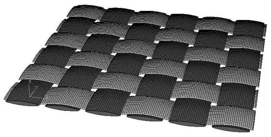
[0055] Example 1 is the simulation of the cutting process of the plain weave method. The weaving method is to cross every other fiber tow. The cross section of the fiber tow is ideally assumed to be an ellipse, with the long diameter of the ellipse being 2 mm and the short diameter being 0.5 mm. , there are six vertically and horizontally, and its fiber weaving structure is as follows: figure 2 shown.

example 2

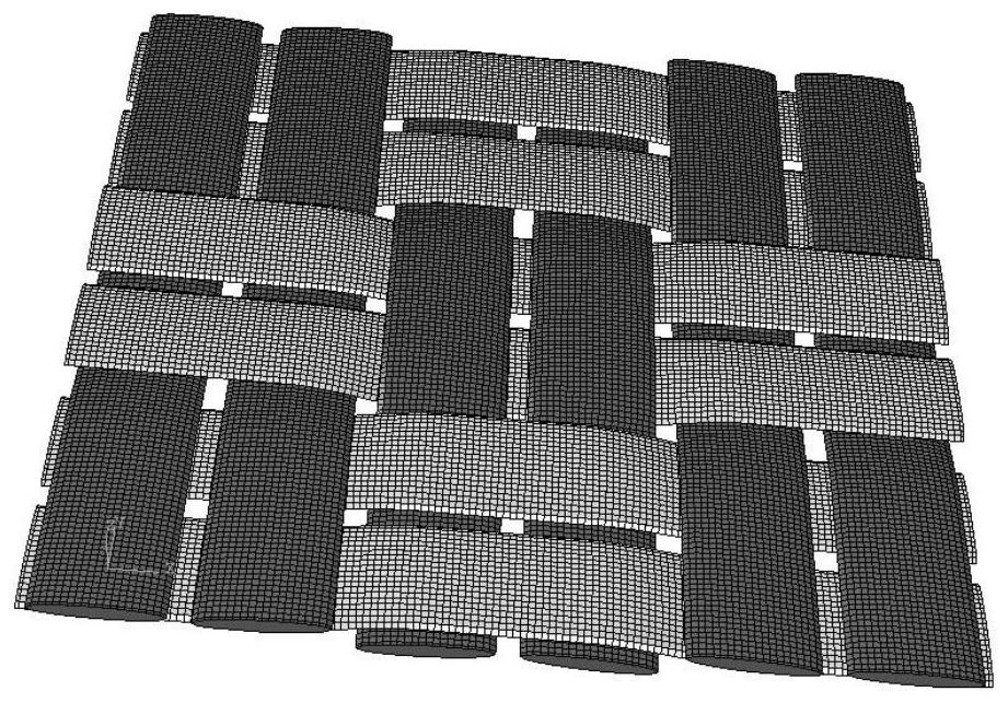
[0056] Example 2 is a simulation of the cutting process of the plain weave structure, which is different from the weaving structure of Example 1 and Example 2. In Example 2, the weaving method crosses every two fiber tows. Also respectively set up six tows in the vertical and horizontal directions in the example 2, and its tow section is identical with example 1, and long diameter is 2mm, and short diameter is 0.5mm, and its fiber weaving structure is as follows: image 3 shown.

example 3

[0057] Example 3 Simulation of the cutting process of the composite material with twill weave structure. Different from Example 1 and Example 2, the tows of Example 3 are crossed every second fiber tow, and the crossing positions of adjacent fiber tows are different by one fiber tow width. The fiber parameters in the model are 2mm in long diameter and 0.5mm in short diameter, and its fiber weaving structure is as follows: Figure 4 shown.

[0058] The matrix model calculates its length, width, and height based on the established fiber model. According to the fiber section, the thickness of the matrix cuboid should be greater than 1mm. Therefore, the length, width, and height of the matrix cuboid are defined as 13mm×13mm×1.1mm.

[0059] For tool models (see attached Figure 8 ), the tool size is set at 4mm in diameter, and the tool size is customized according to the different tool sizes used in drilling. In the examples herein, the cutter diameter is set to 4mm, so that the ...


PUM

PropertyMeasurementUnit
diameteraaaaaaaaaa

Abstract

The invention discloses a modeling method for low-speed cutting process simulation of a fiber reinforced composite material, relates to low-speed cutting processing of carbon fiber composite materials in automobiles and spaceflight, and aims to disperse a mesoscopic model of the composite material into hexahedral grids and consider the influence of a woven structure on cutting in the cutting process. The matrix phase and the reinforcement phase are defined by different material attributes, and the interaction between the fiber tows and the matrix is ignored to realize common node connection. The method specifically comprises the following steps: 1, determining geometric dimensions of models according to braided structures; 2, based on the braided structure, establishing different corresponding models; 3, establishing a periodic boundary condition, and defining a drill bit motion equation; 4, establishing contact attributes among the objects in the model; 5, giving material attributes to the defined fiber tows and a base body, wherein the base body simulates the breaking behavior of the base body in the cutting process through the isotropic elastic-plastic breaking constitutive, and the fiber tows simulate the breaking behavior of the fiber tows in the cutting process through anisotropic materials.

Description

technical field [0001] The invention relates to low-speed cutting processing of carbon fiber composite materials in automobiles and aerospace, and in particular to a finite element model modeling method for simulating low-speed cutting process of fiber-reinforced composite materials. Background technique [0002] Carbon fiber composite materials are widely used in the fields of automobiles and aerospace because of their excellent mechanical properties, such as exterior parts of automobiles and aircrafts. However, the processing of carbon fiber composite materials is also a problem. It is a typical difficult-to-process material. Carbon fiber composite materials are prone to processing defects during processing, especially when drilling holes are more prone to defects such as delamination and burrs. In terms of macroscopic theoretical research, it is usually established to stack a single layer into multiple layers to simulate the mechanical behavior of carbon fiber composite m...

Claims


Application Information

Patent Timeline
Patent Type & Authority Applications(China)
IPC IPC(8): G06F30/23G06F30/17G06F113/26
CPCG06F30/23G06F30/17G06F2113/26
Inventor 马叙杨秀兵丁燕红
Owner TIANJIN UNIVERSITY OF TECHNOLOGY
Why Eureka
Try Eureka