Angular power division waveguide structure applied to dielectric loading gyrotron traveling wave tube

A medium-loading and sub-waveguide technology, applied in the direction of waveguides, waveguide-type devices, coupling devices of transit-time electron tubes, etc., to achieve the effects of improving power capacity, reducing electromagnetic power density, and high-efficiency energy conversion

Active Publication Date: 2021-04-06
UNIV OF ELECTRONICS SCI & TECH OF CHINA
View PDF10 Cites 4 Cited by
  • Summary
  • Abstract
  • Description
  • Claims
  • Application Information

AI Technical Summary

Problems solved by technology

[0004] In order to solve the technical bottleneck of the high average power output of the traditional medium-loaded gyrotraveling wave tube

Method used


Image

  • Angular power division waveguide structure applied to dielectric loading gyrotron traveling wave tube
  • Angular power division waveguide structure applied to dielectric loading gyrotron traveling wave tube
  • Angular power division waveguide structure applied to dielectric loading gyrotron traveling wave tube

Examples


Embodiment Construction

[0024] Below in conjunction with a design example and accompanying drawing, the present invention is described in further detail:

[0025] The technical index requirements for the angular power division waveguide structure applied in the medium-loaded gyrotraveling wave tube:

[0026] Circular waveguide working mode: TE 01 mode; working frequency band: U-band (45GHz-52GHz);

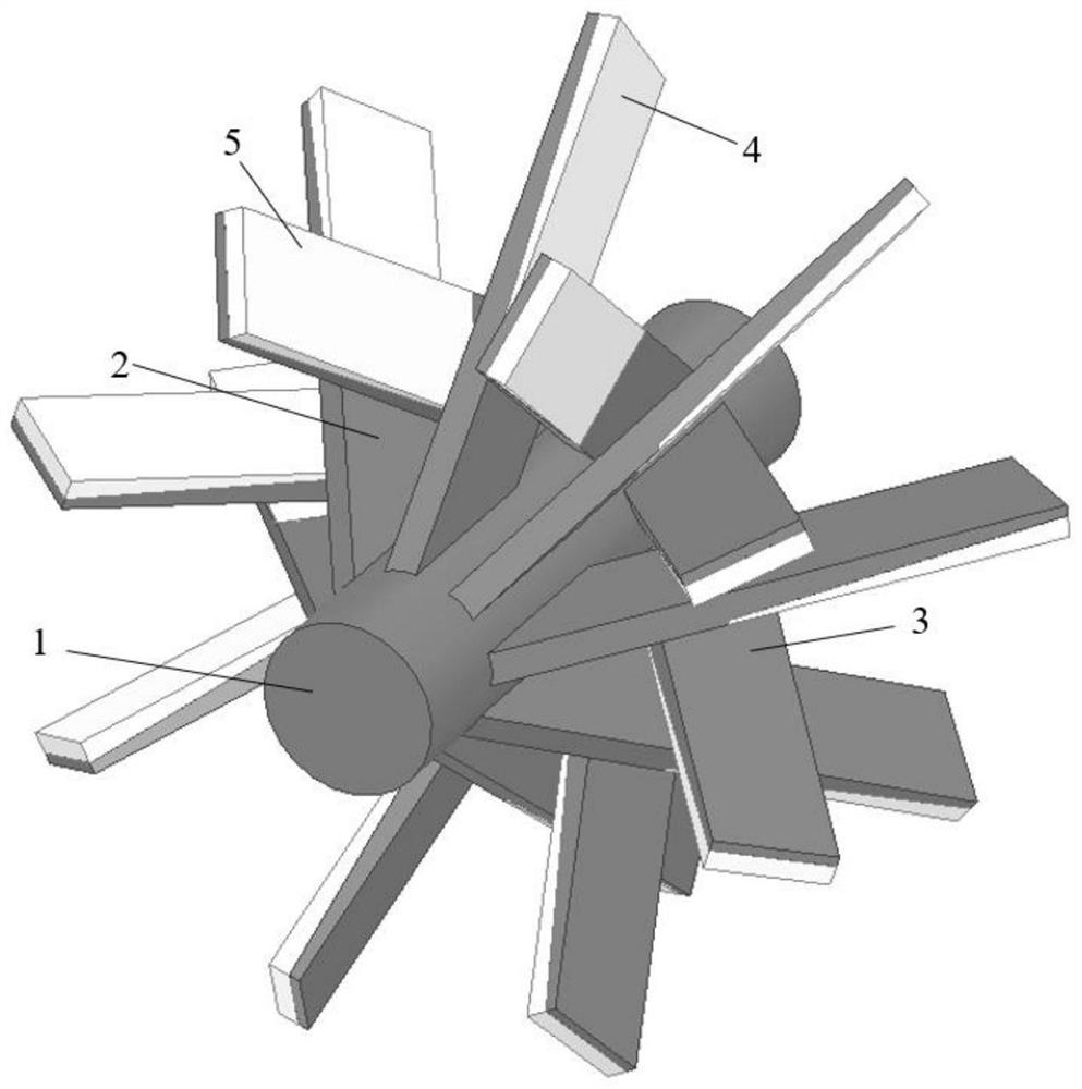
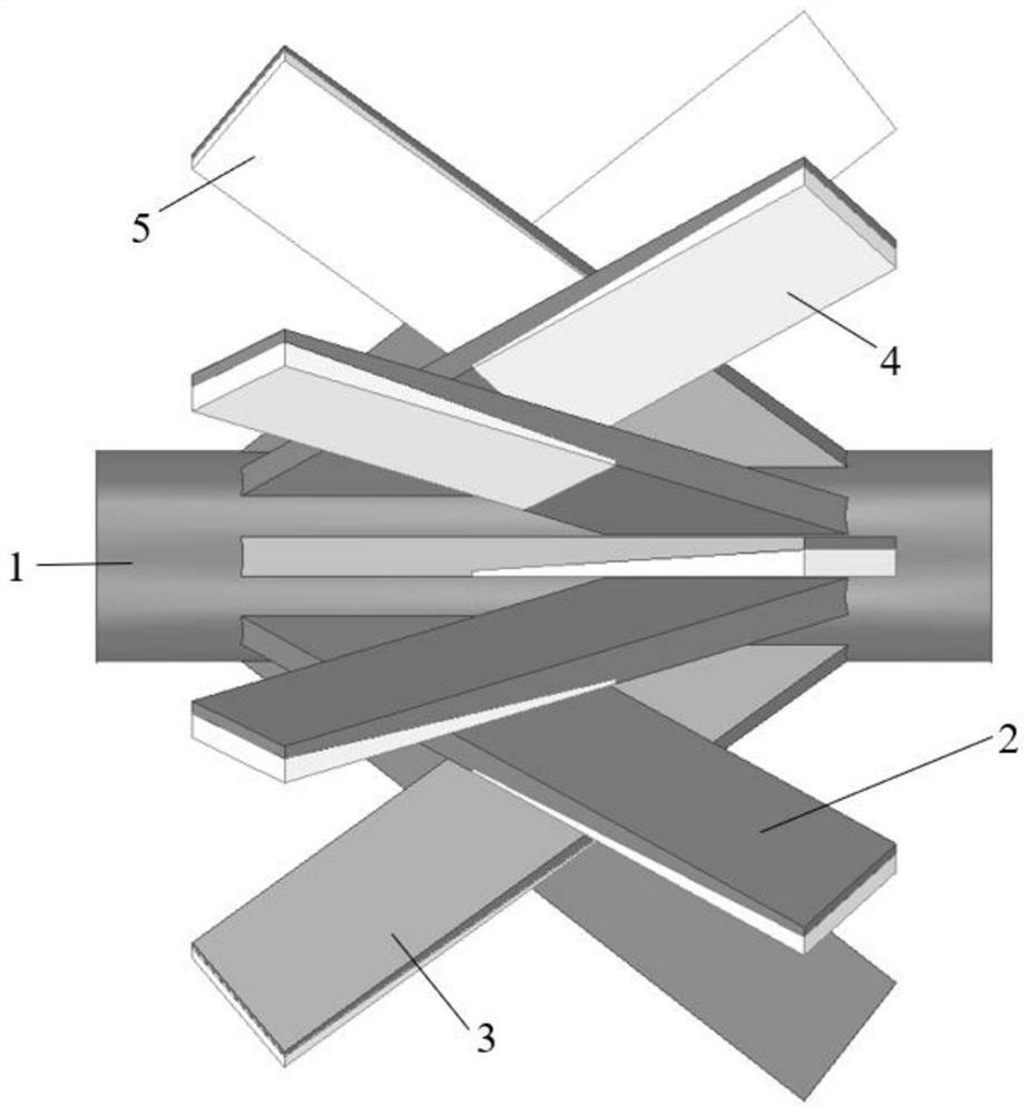
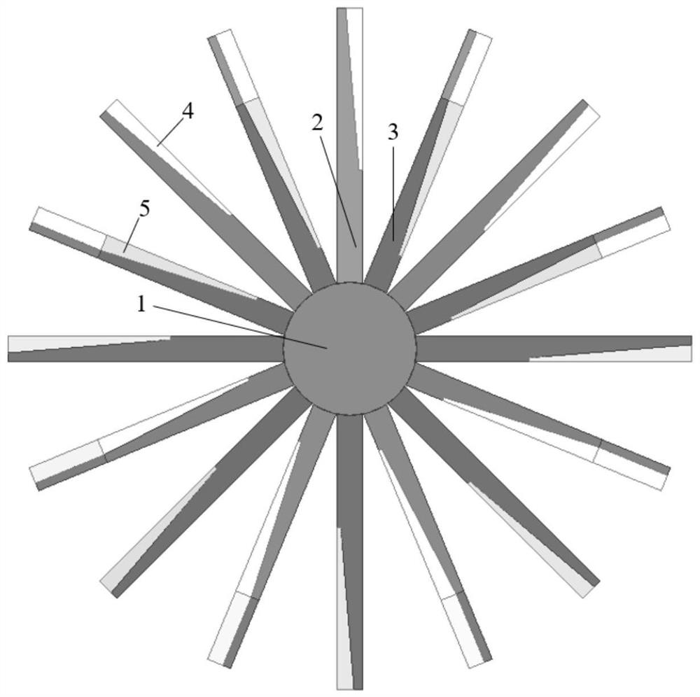
[0027] Its structure is as Figure 1-5 shown. Including: circular waveguide (1), forward angular power splitting waveguide (2), reverse angular power splitting waveguide (3), attenuating ceramic sheet (4) loaded in the forward angular power splitting waveguide, An attenuating ceramic sheet (5) loaded into the power splitting waveguide.

[0028] in:

[0029] Circular waveguide (main waveguide) (1): radius 4.04 mm, length 34 mm;

[0030] Forward angular power splitting waveguide (2): including 8 oblique non-standard rectangular waveguides that are uniformly distributed angularly on the outer wall of t...


PUM


Abstract

The invention discloses an angular power division waveguide structure applied to a dielectric loading gyrotron traveling wave tube, belonging to the technical field of microwave and millimeter wave electric vacuum devices. The angular power division waveguide structure of the invention is arranged between a medium loading interaction section and an output waveguide section; the angular power division waveguide structure comprises a circular waveguide, N forward angular power division waveguides and N reverse angular power division waveguides; the forward angular power dividing waveguides are oblique rectangular waveguides which are uniformly distributed along the angular direction of the outer wall of the circular waveguide; and the reverse angular power dividing waveguides are oblique rectangular waveguides which are uniformly distributed along the angular direction of the outer wall of the circular waveguide. After electromagnetic waves generated by the gyrotron traveling wave tube in a pre-clustering stage enter the angular power division waveguide structure, most of electromagnetic wave energy is directly transmitted into the angular power division waveguide and then absorbed by a wave absorbing structure; and the angular power division waveguide structure increases a dissipation area, improves the average power capacity of the gyrotron traveling wave tube, and effectively shortens the length of a medium loading section.

Description

technical field [0001] The invention relates to the technical field of microwave and millimeter wave electric vacuum devices, in particular to an angular power division waveguide structure applied to a medium-loaded gyrotraveling wave tube. Background technique [0002] The gyrotron is an important high-power millimeter-wave source. It has the characteristics of broadband and high power, and has broad application prospects in military and civilian fields such as radar, communication, electronic countermeasures, material processing, controlled thermonuclear fusion plasma heating, and environmental protection, so it has been highly valued internationally and domestically. [0003] After years of development, the gyro-traveling-wave tube has derived a variety of tubular structures, among which the gyro-traveling-wave tube with a medium-loaded structure is a very successful gyro-traveling-wave tube structure. The gyro-traveling-wave tube includes sequentially connected input wav...

Claims


Application Information

Patent Timeline
Patent Type & Authority Applications(China)
IPC IPC(8): H01P3/127H01P3/12H01J23/36
CPCH01J23/36H01P3/12H01P3/127
Inventor 徐勇郑智斌毛娅刘智航田辰彦王高磊
Owner UNIV OF ELECTRONICS SCI & TECH OF CHINA
Why Eureka
Try Eureka