Cutting machine with positioning and guiding structure for scaffold fastener production
A technology of positioning guide and fasteners, applied in the field of mechanical processing, can solve the problems of material waste, large processing workload, poor quality of manual cutting, and harsh working conditions, etc., to achieve the effect of saving materials, improving cutting quality, and reducing workload
- Summary
- Abstract
- Description
- Claims
- Application Information
AI Technical Summary
Problems solved by technology
Method used
Image

Examples
Embodiment 1
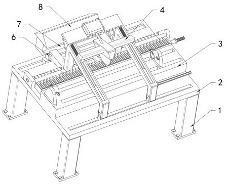
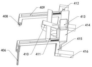
[0022] refer to Figure 1-4 , a cutting machine with a positioning and guiding structure for the production of scaffold fasteners, including a bearing plate 2, a clamping mechanism 3 is provided on one side of the top of the bearing plate 2, a guiding mechanism 4 is provided on the other side, and the guiding mechanism 4 One side is provided with a support block 8, and the guide mechanism 4 includes two support frames 415 that are inverted U-shaped in front view, and the bottom of one side of the two support frames 415 is provided with an ear seat 6, and one of the two support frames 415 The vertical sections are rotatably connected with the two lugs 6 through connecting rods 416, for the two support frames 415 to rotate to one side, and the bottom of the other vertical section of the two support frames 415 is equipped with a moving wheel 408, For adjustment, the bottoms of the two lugs 6 are slidingly connected to the top of the bearing plate 2 through sliders for position ad...
Embodiment 2
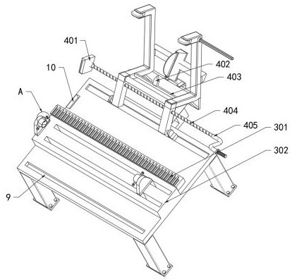
[0027] refer to Figure 1-4 , the clamping mechanism 3 includes a cutting table 302 fixedly connected to the top side of the carrier plate 2, the cutting table 302 is located at the bottom of the horizontal section of the two supporting frames 415, and sleeves 303 are arranged on both sides of the top of the cutting table 302 , both sides of the two sleeves 303 are threaded with a screw rod 306 that runs through the sleeve 303, and one end of the corresponding extension of the two screw rods 306 is fixedly connected with a collision plate 305, and the opposite end of the two sleeves 303 Both sides are fixedly connected with a fixed block 304 , one of the two fixed blocks 304 is fixedly connected with the cutting table 302 , and the other fixed block 304 is slidably connected with the cutting table 302 through a slider.
[0028] One side of the cutting table 302 is fixedly connected with a scale plate 301, and the top of the scale plate 301 is provided with a pointing plate 402...
PUM
 Abstract
Description
Claims
Application Information
 - R&D
- Intellectual Property
- Life Sciences
- Materials
- Tech Scout
- Unparalleled Data Quality
- Higher Quality Content
- 60% Fewer Hallucinations
Browse by: Latest US Patents, China's latest patents, Technical Efficacy Thesaurus, Application Domain, Technology Topic, Popular Technical Reports.
© 2025 PatSnap. All rights reserved.Legal|Privacy policy|Modern Slavery Act Transparency Statement|Sitemap|About US| Contact US: help@patsnap.com