Adjustable clamp structure for steel pipe welding for steel structure buildings

An adjustable technology for construction, applied in the direction of welding equipment, auxiliary welding equipment, welding/cutting auxiliary equipment, etc., can solve the problems of instability, easy deviation of welding points, increase of labor intensity of staff, etc., to achieve convenient welding, Improved utility, improved convenience, and continuous effects

Pending Publication Date: 2021-04-09
湖南鸿云钢模科技有限公司
View PDF8 Cites 0 Cited by
  • Summary
  • Abstract
  • Description
  • Claims
  • Application Information

AI Technical Summary

Problems solved by technology

[0004] In the prior art, steel pipes and other parts need to be welded during the processing of steel pipes, so the steel pipes need to be clamped, but most of the clamping work is manually clamped, but manual assembly The method has unstable factors, which affects the assembly effect and assembly efficiency to a certain extent;
[0005] After the clamping work is completed, the steel pipe cannot be rotated. Only by frequently disassembling and re-clamping the steel pipe by the staff can the welding at different positions of multiple angles be completed, but frequent disassembly will increase the labor intensity of the staff and It makes the welding point prone to deviation, resulting in the quality of the steel pipe being affected

Method used


Image

  • Adjustable clamp structure for steel pipe welding for steel structure buildings
  • Adjustable clamp structure for steel pipe welding for steel structure buildings
  • Adjustable clamp structure for steel pipe welding for steel structure buildings

Examples


Embodiment Construction

[0030] In order to make the technical means, creative features, goals and effects achieved by the present invention easy to understand, the present invention will be further described below in conjunction with specific embodiments.

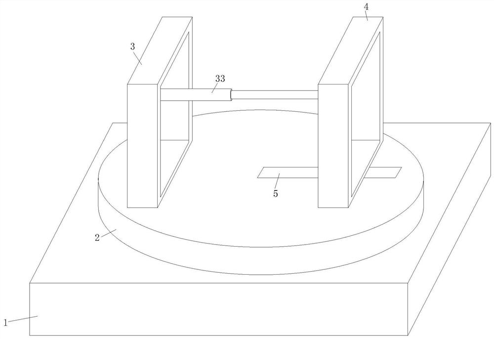
[0031] Such as Figure 1-Figure 8 As shown, the adjustable fixture structure for steel pipe welding of a steel structure building according to the present invention includes a base 1, a rotating table 2, a first clamping mechanism 3, a second clamping mechanism 4 and a sliding mechanism 5. The top of the base 1 is connected with a rotary table 2, the top of the rotary table 2 is fixedly installed with a first clamping mechanism 3, and the top of the rotary table 2 is slidably connected with a second clamping mechanism 4 through a sliding mechanism 5, The first clamping mechanism 3 and the second clamping mechanism 4 have the same internal structure, and the two first clamping mechanisms 3 and the second clamping mechanism 4 are movably connected b...


PUM


Abstract

The invention relates to the field of steel structure buildings, in particular to an adjustable clamp structure for steel pipe welding for steel structure buildings. The adjustable clamp structure comprises a base, a rotary table, a first clamping mechanism, a second clamping mechanism and a sliding mechanism; the top of the base is rotatably connected with the rotary table, and the first clamping mechanism is fixedly mounted at the top of the rotary table; and the top of the rotary table is slidably connected with the second clamping mechanism through the sliding mechanism. According to the adjustable clamp structure for steel pipe welding for the steel structure buildings, by arranging a driving device, a worm wheel motor is used for promoting a gear vertical rod to drive a gear transverse rod to rotate through a worm, so that a threaded pipe drives a deflection rod to drive clamping plates to do lifting motion through a nut sleeve, the two clamping plates clamp a steel pipe, the adjustable clamp structure can effectively clamp steel pipes of different specifications, the purpose that the steel pipes of various different specifications can still be clamped is achieved, and the practicability of the adjustable clamp structure is improved.

Description

technical field [0001] The invention relates to the field of steel structure buildings, in particular to an adjustable fixture structure for welding steel pipes used in steel structure buildings. Background technique [0002] Welding, also known as welding and welding, is a manufacturing process and technology for joining metal or other thermoplastic materials by heating, high temperature or high pressure. Welding technology is mainly applied to the metal base metal, commonly used arc welding, argon arc welding, CO2 shielded welding, oxygen-acetylene welding, laser welding, electroslag pressure welding, etc. Non-metallic materials such as plastics can also be welded. [0003] During the use of steel pipes, it is often necessary to weld two steel pipes. In order to make the nozzles of the steel pipes flush and the center lines of the steel pipes aligned, those skilled in the art have designed various steel pipe welding and clamping equipment. [0004] In the prior art, steel...

Claims


Application Information

Patent Timeline
Patent Type & Authority Applications(China)
IPC IPC(8): B23K37/053
CPCB23K37/0533B23K37/0538
Inventor 成衡军高多安
Owner 湖南鸿云钢模科技有限公司
Why Eureka
Try Eureka