
Underwater robot walking mechanism

An underwater robot and walking mechanism technology, which is applied to underwater ships, underwater operation equipment, motor vehicles, etc., can solve problems such as affecting work efficiency and progress, unable to complete tasks, and robots getting stuck, and achieve the effect of improving buoyancy.

Active Publication Date: 2022-06-14
NINGBO DAHONGYING UNIV
View PDF0 Cites 0 Cited by
  • Summary
  • Abstract
  • Description
  • Claims
  • Application Information

AI Technical Summary

Problems solved by technology

[0002] Underwater robots are often used in water quality surveys, biological sample collection, etc. Due to the complex underwater conditions and a large amount of silt on the underwater ground, underwater robots are very easy to sink into the silt during walking, which affects work efficiency and progress, and in severe cases, it may cause the robot to be stuck or damaged, not only unable to complete the task, but also causing additional losses to the user

Method used


Image

  • Underwater robot walking mechanism
  • Underwater robot walking mechanism

Examples


Embodiment 1

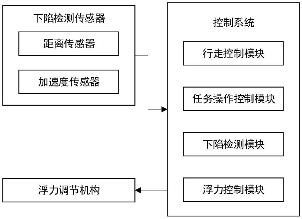
[0023] The walking mechanism of the underwater robot in this embodiment includes a chassis, and the chassis is provided with a four-legged walking mechanism, a buoyancy adjustment mechanism and an electric control system.

[0024] The multi-legged walking mechanism is used to drive the chassis to move. The multi-legged walking mechanism includes several walking feet. In this implementation, four walking feet are used. The walking feet are designed with reference to the prior art, and include a plurality of foot segments. A steering gear is arranged on the hinge shaft to control the rotation of the foot joints, and walking is realized through the rotation and cooperation of the foot joints of a plurality of walking feet.

[0025] There is a sag detection sensor on the walking foot, the sag detection sensor is connected with the control system signal, and the sag detection sensor is used to send the detection data to the control system; in this implementation, the sag detection s...

Embodiment 2

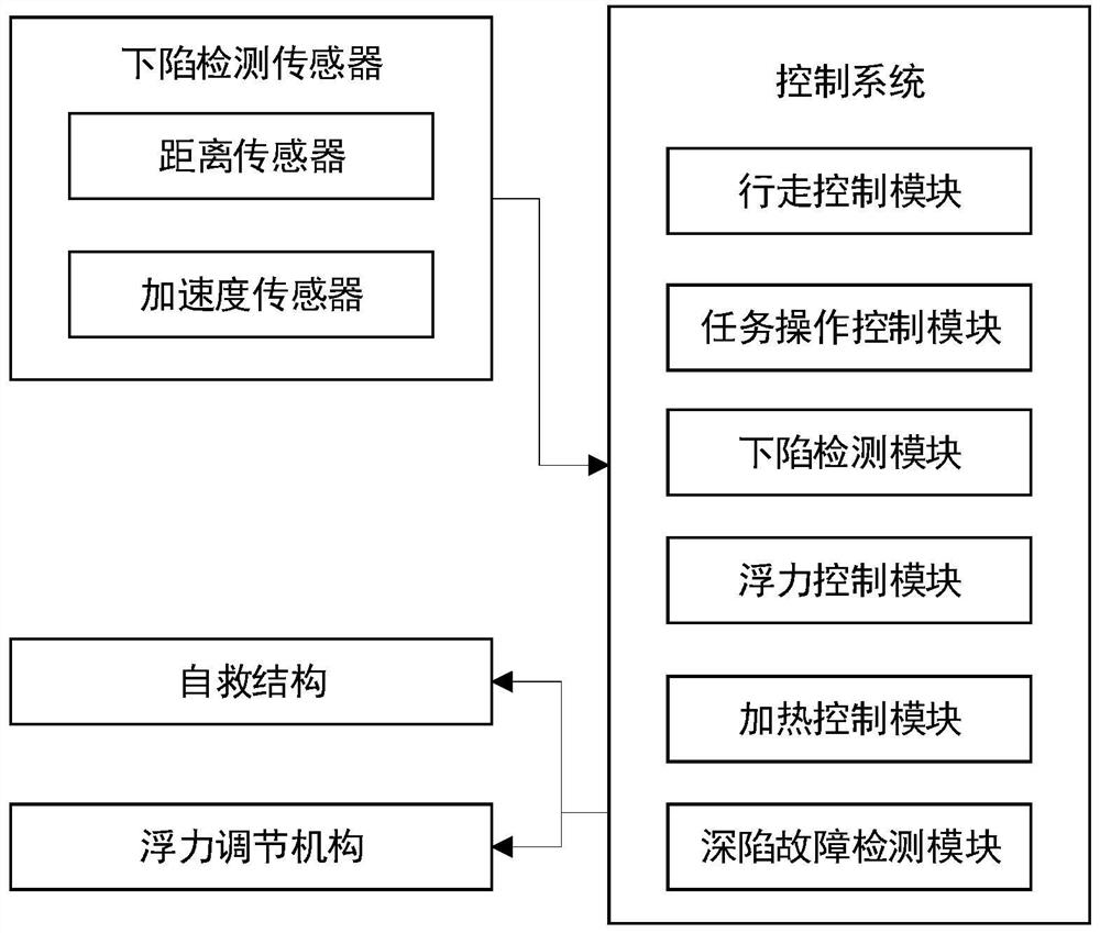
[0032] like figure 2 As shown in the figure, the difference between this embodiment and the first embodiment is that in this embodiment, a self-rescue structure is also included, and the self-rescue structure includes a compressed air bag and a gas generating device. , sodium azide, potassium nitrate and silicon dioxide, the compression airbag is communicated with the shell, in this implementation, the shell is provided with a reaction chamber and a discharge pipe communicated with the reaction chamber, heater, sodium azide, potassium nitrate and The silicon dioxide is arranged in the reaction chamber, the phosphor is arranged in the discharge pipe, the two ends of the discharge pipe are provided with sealing films to isolate the phosphor powder, the discharge pipe is connected to the compressed air bag, the heater is connected with the signal of the control system, and the control system also includes a deep fault The detection module, the deep-sinking fault detection module...


PUM


Abstract

The present invention relates to the technical field of robot control systems, specifically the walking mechanism of an underwater robot, including: a chassis on which a quadruped walking mechanism and a buoyancy adjustment mechanism are arranged; the multi-legged walking mechanism is used to drive the chassis to move, and the multi-legged walking mechanism includes A number of walking feet, on which there are subsidence detection sensors; a buoyancy adjustment mechanism, which is used to provide buoyancy for the chassis and adjust the buoyancy according to the signal of the control system; it also includes a subsidence detection module, a buoyancy control module, and a subsidence detection module. Detect the sensor data, and judge whether the walking foot is subsidence according to the data of the subsidence detection sensor; the buoyancy control module is used to control the buoyancy adjustment mechanism to increase the buoyancy after the subsidence detection module detects that the walking foot is subsidence. The underwater robot walking mechanism of the present application can prevent the underwater robot from sinking deep into the bottom of the water and affecting the task completion efficiency.

Description

technical field [0001] The invention relates to the technical field of robot control systems, in particular to a walking mechanism of an underwater robot. Background technique [0002] Underwater robots are often used in water quality surveys, biological sample collection, etc. Due to the complex underwater conditions and the existence of a large amount of silt on the underwater ground, the underwater robot is very easy to sink into the silt during the walking process, affecting work efficiency and efficiency. progress, and in severe cases, the robot may be stuck or damaged, not only unable to complete the task, but also causing additional losses to the user. SUMMARY OF THE INVENTION [0003] The present invention is intended to provide a walking mechanism for an underwater robot, which can prevent the underwater robot from sinking into the bottom of the water and affecting the task completion efficiency. [0004] This application provides the following technical solution...

Claims


Application Information

Patent Timeline
Patent Type & Authority Patents(China)
IPC IPC(8): B63C11/52B63G8/22
CPCB63C11/52B63G8/22
Inventor 陈苗青
Owner NINGBO DAHONGYING UNIV
Learn More