Construction equipment and method for an underground comprehensive pipe gallery

A technology for construction equipment and comprehensive pipe gallery, applied in artificial islands, water conservancy projects, underwater structures, etc., can solve problems such as poor bearing capacity, increased construction costs, and large cement consumption, and achieve increased section bending stiffness, Reduced footprint, easy disassembly and installation

Active Publication Date: 2022-01-28
WUHAN SURVEYING GEOTECHN RES INST OF MCC
View PDF0 Cites 1 Cited by
  • Summary
  • Abstract
  • Description
  • Claims
  • Application Information

AI Technical Summary

Problems solved by technology

Since cast-in-place construction requires a large construction space, and the amount of earth excavation is also large, the concrete can only be removed when it reaches the design strength. The construction period is long, the cost is high, the construction procedures are complicated, and the site maintenance conditions are poor, so the project quality cannot be guaranteed. A large amount of concrete is required during the construction process, which is less environmentally friendly. The construction of prefabricated pipe galleries is more environmentally friendly. However, due to the huge tonnage of prefabricated pipe galleries, the requirements for hoisting and transportation equipment are high, and the existing construction equipment for pipe galleries cannot meet the construction conditions of prefabricated pipe galleries. , leading to great difficulties in the construction of prefabricated pipe gallery
[0004] At present, the protection piles for the foundation pit of the pipe gallery mainly include SMW piles, U-shaped steel sheet piles, etc. Among them, the SMW piles play the role of water stop through the cement soil after mixing, but the construction process needs to consume a lot of cement, and the cement is in the process of transportation and mixing. A large amount of dust, waste mud and replacement soil will be generated in the environment, causing environmental pollution, which does not meet the ecological and environmental protection requirements of the current urban comprehensive pipe gallery infrastructure construction
Although the U-shaped steel sheet pile has a good water-stop effect, its bending resistance is weak, and it cannot reliably support the lateral earth pressure of the foundation pit. Moreover, the existing U-shaped steel sheet piles are all front and back staggered splicing, and the area occupied Larger, this will cause the two sides of the steel sheet pile to be not on the same plane, and its inner and outer surfaces are concave and convex, which is very convenient for connecting I-beams or other components in the later stage, and if heavy equipment is erected on it, Its bearing capacity is relatively poor
[0005] For the construction process of the foundation pit of the pipe gallery, heavy equipment is required for the transportation of the soil in the foundation pit, the lifting and installation of the prefabricated pipe gallery, and the lifting and installation of the pipeline, and the ground outside the foundation pit of the general pipe gallery They are relatively narrow. Conventional truck cranes or crawler cranes need to stand on the ground outside the foundation pit for lifting. For narrow foundation pits, these ordinary lifting equipment cannot be used normally, so they are generally used in foundation pit enclosure. Gantry lifting equipment is erected above the structure, but the load-bearing capacity of the existing U-shaped steel sheet piles cannot meet the requirements
In addition, because the foundation pit of the pipe gallery generally extends relatively long, ordinary fixed gantry cranes are not suitable. The existing walking gantry cranes have track type and ordinary walking type. The ordinary walking gantry crane is not very smooth for the bottom The construction site is not suitable for the track-type gantry. It is necessary to lay the track first and then erect the gantry; the existing foundation pit enclosure structure is not very convenient when laying the track, especially when the steel sheet pile is laying the track. In addition, the gauge of the track is fixed, and it is very troublesome to disassemble and replace different tracks
Moreover, the width of the existing gantry cranes is fixed, but the width of the foundation pit of the pipe gallery will change due to the influence of the terrain or surrounding buildings. The foundation pits of different widths need to be erected with gantry cranes of different widths. The erection of the track, the gantry crane, and the disassembly and assembly of the track are more complicated, resulting in a significant increase in construction costs

Method used


Image

  • Construction equipment and method for an underground comprehensive pipe gallery
  • Construction equipment and method for an underground comprehensive pipe gallery
  • Construction equipment and method for an underground comprehensive pipe gallery

Examples


Embodiment Construction

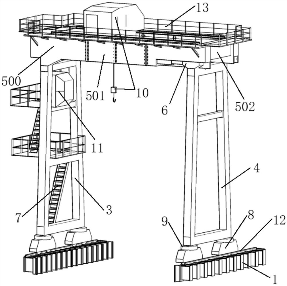
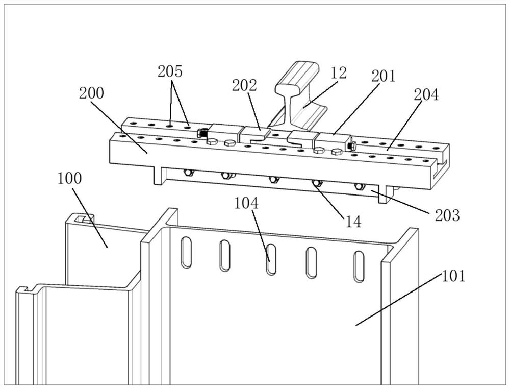
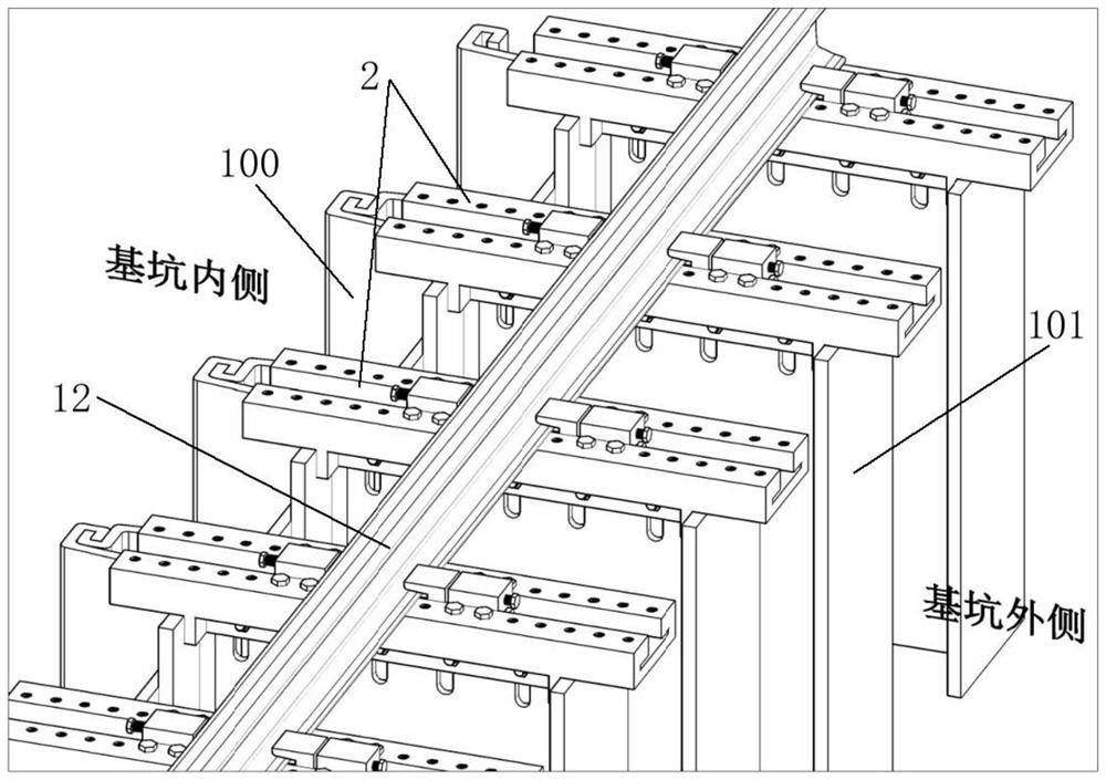
[0051] The present invention will be further described below in conjunction with drawings and embodiments. attached Figures 1 to 14 All are drawings of embodiments, drawn in a simplified manner, and are only used for the purpose of clearly and concisely illustrating the embodiments of the present invention. The following technical solutions shown in the drawings are specific solutions of the embodiments of the present invention, and are not intended to limit the scope of the claimed invention. Based on the embodiments of the present invention, all other embodiments obtained by persons of ordinary skill in the art without creative efforts fall within the protection scope of the present invention.

[0052] In the description of the present invention, it should be understood that the orientations or positional relationships indicated by the terms "upper", "lower", "inner", "outer", "left", "right" etc. are based on those shown in the accompanying drawings. Orientation or posit...


PUM


Abstract

The invention provides construction equipment and a construction method for an underground comprehensive pipe gallery. The construction equipment includes a foundation pit enclosure structure, track connectors, walking rails and gantry lifting devices; the foundation pit enclosure structure includes a plurality of composite piles composed of U-shaped steel sheet piles and H-shaped steel pillars interlocked side by side , the track connector includes a base and two sets of track positioning adjustment members symmetrically installed on the base, the bottom of the track connector is connected with the H-shaped steel pillar web of the composite pile, and rails are installed on the track connector; The device includes a fixed outrigger, a span adjustment outrigger, a bridge frame connecting the two outriggers and a traveling mechanism, and the gantry lifting device is slidingly connected with the traveling rail through the traveling mechanism. The invention combines foundation pit support and hoisting equipment into one body, and makes full use of each other, which not only enhances the integrity of the support system, but also reduces the occupied area of ​​rail laying, reduces environmental pollution, and after the construction is completed, All equipment is recyclable.

Description

technical field [0001] The present invention relates to the construction field of underground comprehensive pipe gallery, in particular to a construction equipment and method for underground comprehensive pipe gallery. Purpose. Background technique [0002] Urban comprehensive utility corridor is a kind of urban infrastructure with the characteristics of modernization, scientization and intensification (Tan Zhongsheng, Chen Xueying, Wang Xiuying, etc. Construction management mode and key technology of urban underground comprehensive utility corridor[J]. Tunnel construction, 2016, 36(10): 1177.). It refers to the construction of public tunnels in the city's underground for the centralized laying of municipal pipelines such as power, communications, radio and television, water supply, drainage, heat, and gas, which is conducive to solving the problems of repeated excavation of roads, dense overhead line networks, Frequent pipeline accidents and other issues. As a municipal ...

Claims


Application Information

Patent Timeline
Patent Type & Authority Patents(China)
IPC IPC(8): E02D29/045
CPCE02D29/10
Inventor 陈斌肖玉成李春磊谢亮丁洪元
Owner WUHAN SURVEYING GEOTECHN RES INST OF MCC
Why Eureka
Try Eureka