
Solar-driven pressurized jet refrigeration system

A refrigeration system and solar energy technology, which is applied to machines, refrigerators, refrigeration components, etc. using solar energy, can solve the problems such as the failure of the system to operate normally, the ejector injection coefficient is not high, and the irreversible throttling loss.

Active Publication Date: 2021-04-09
浙江省送变电工程有限公司 +2
View PDF10 Cites 6 Cited by
  • Summary
  • Abstract
  • Description
  • Claims
  • Application Information

AI Technical Summary

Problems solved by technology

[0004] According to existing literature, the outlet back pressure of the injector must be lower than the critical back pressure for the injector to operate efficiently, otherwise performance will be deteriorated due to the significantly lower injection coefficient
And due to the existence of internal mixing loss, wall friction and shock wave loss, the injection coefficient of the injector is not high
Therefore, there are the following problems in the solar jet refrigeration system: 1. The solar radiation is transient, and the performance of the solar jet refrigeration system is unstable
The system does not function properly at night without solar power
2. The coefficient of thermal performance of the system (cooling capacity / heat consumption), that is, the efficiency of heat energy utilization is low, and the area of ​​solar collector panels required is too large
3. The solar jet refrigeration system needs to be equipped with a heater to maintain a constant cooling capacity in rainy days, but due to the low utilization rate of heat energy, this measure is not economical
However, the high-temperature and high-pressure gaseous refrigerant is directly condensed and throttled to the low-temperature and low-pressure liquid refrigerant, and there is a large amount of irreversible throttling loss.

Method used


Image

  • Solar-driven pressurized jet refrigeration system

Examples


Embodiment Construction

[0025] The technical solution of the present invention will be further described in detail below in conjunction with the accompanying drawings.

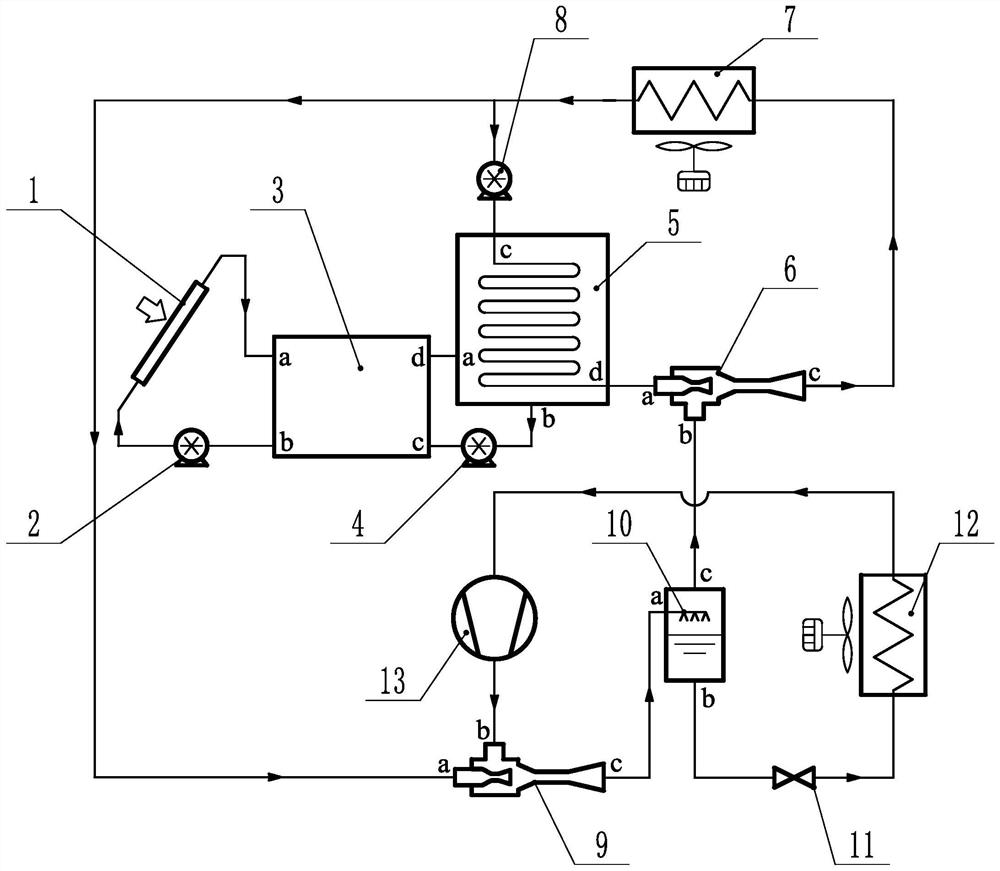
[0026] Such as figure 1As shown, a solar-driven pressurized injection refrigeration system includes a solar heat collection subsystem and a pressurized injection subsystem. In the solar heat collection subsystem, the outlet of the solar heat collector 1 and the high-temperature water inlet of the heat storage tank 3 a Connected at both ends, the low-temperature water outlet b of the hot water storage tank 3 is connected with the inlet of the first water pump 2, the outlet of the first water pump 2 is connected with the inlet of the solar collector 1, and the high-temperature water outlet d of the hot water storage tank 3 is connected with the generator 5 for heating The inlet a on the water side is connected, the outlet b on the hot water side of the generator 5 is connected to the inlet of the second water pump 4, and the outlet of ...


PUM


Abstract

The invention discloses a solar-driven pressurized jet refrigeration system, and relates to the field of refrigeration systems. In an existing solar pressurization jet refrigeration system, the heat exchange temperature difference of an intermediate heat exchanger is large, further improvement of system performance is affected, and a large amount of irreversible throttling losses exist. The solar-driven pressurized jet refrigeration system comprises a solar heat collector, a first water pump, a heat storage water tank, a second water pump, a generator, a steam ejector, a condenser, a working medium pump, a two-phase ejector, a gas-liquid separator, an expansion valve, an evaporator and a scroll compressor. The scroll compressor is arranged at the inlet of the two-phase ejector, so that the pressure of a driving fluid inlet can be effectively improved, throttling loss recovery is realized, the pressure of a secondary fluid inlet of the steam ejector is improved, the performance of the steam ejector is improved, abnormal work is avoided, and the solar energy utilization rate and the system operation stability are improved; and the scroll compressor, the steam ejector and the two-phase ejector jointly bear the compression effect of a refrigerant, so that the power consumption is reduced, and the system energy efficiency is improved.

Description

technical field [0001] The invention relates to the field of refrigeration systems, in particular to a solar-driven pressurized jet refrigeration system. Background technique [0002] At present, the vapor compression refrigeration system is widely used in the field of refrigeration and air conditioning, but the mechanical compression refrigeration system driven by electric energy consumes too much fossil energy and causes many environmental problems. Energy and environmental problems are becoming more and more serious, and people are turning their attention to refrigeration systems that use renewable energy, such as absorption, adsorption and injection refrigeration systems. [0003] The ejection refrigeration system has simple structure, reliable operation, low cost and maintenance cost, and can effectively compete with complex and expensive absorption refrigeration systems when the temperature of the heat source is lower than 80°C. Solar energy is a clean and renewable e...

Claims


Application Information

Patent Timeline
IPC IPC(8): F25B25/00F25B19/04F25B1/04F25B41/31F25B27/00
CPCF25B25/00F25B19/04F25B1/04F25B27/005F25B2600/2513
Inventor 黄潇治储旺准洪楠黄钢
Owner 浙江省送变电工程有限公司
Learn More