
Chemical fiber drying device

A chemical fiber and drying device technology, which is applied in the direction of heating device, drying solid materials, dry cargo handling, etc., can solve the problems of low drying efficiency, poor drying effect, complex structure of air dryer, etc., achieve high drying efficiency and prolong the residence time , good drying effect

Active Publication Date: 2021-04-09
临沂市兰山区腾威塑料有限公司
View PDF11 Cites 0 Cited by
  • Summary
  • Abstract
  • Description
  • Claims
  • Application Information

AI Technical Summary

Problems solved by technology

[0003] At present, when processing chemical fibers, it is usually necessary to dry the chemical fibers to ensure the quality of the finished products in the subsequent processing of chemical fibers. In the prior art, the drying of chemical fibers is mostly achieved by air dryers. The chemical fiber is transported to the inside of the air dryer, and the air drying of the chemical fiber is realized by the action of the hot air flow. However, the existing air dryer has a relatively complicated structure, and the drying effect is poor and the drying efficiency is relatively low, which cannot guarantee the effective air drying of the chemical fiber.

Method used


Image

  • Chemical fiber drying device
  • Chemical fiber drying device
  • Chemical fiber drying device

Examples


Embodiment 1

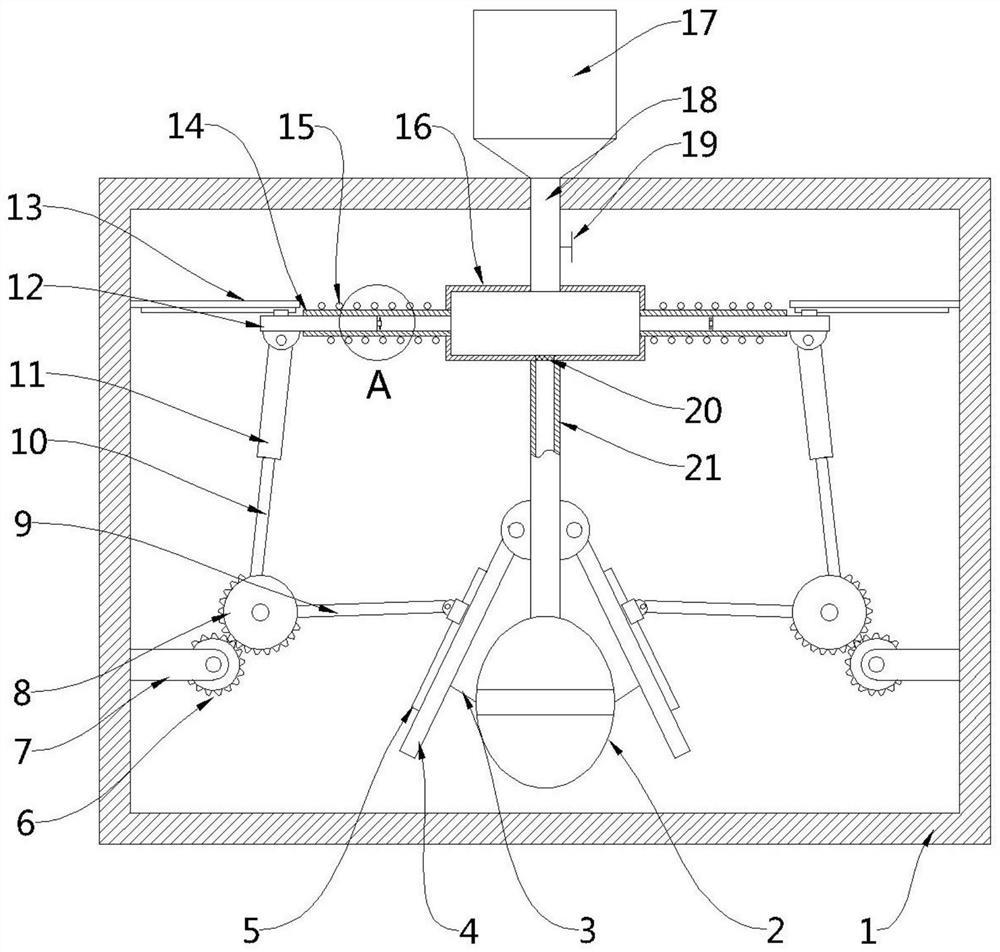
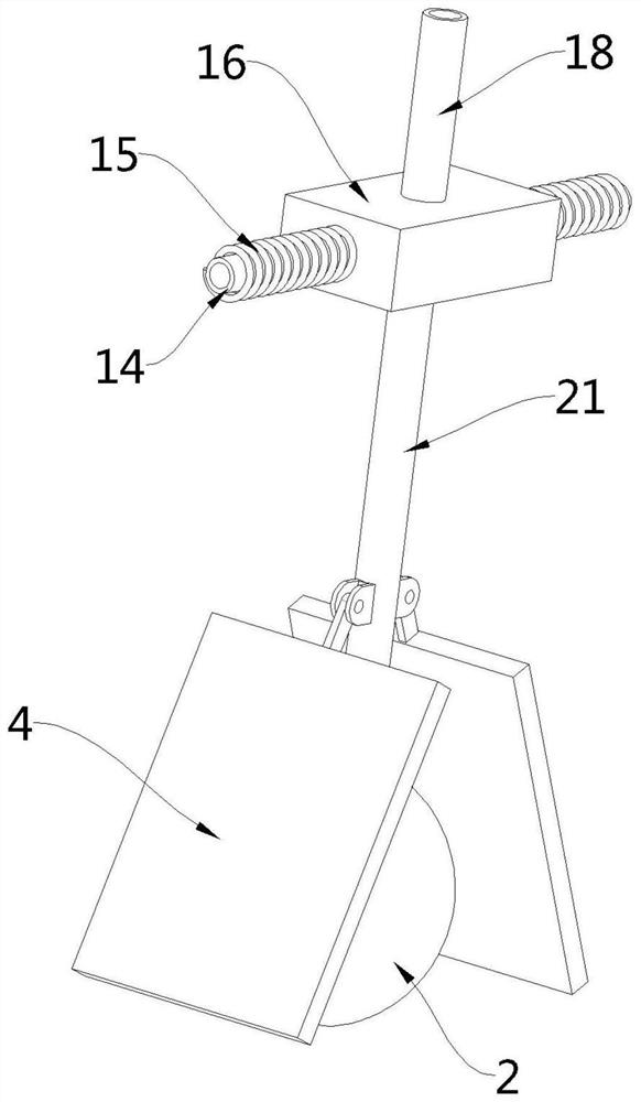
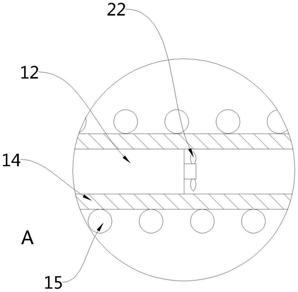
[0024] see Figure 1-3 , the present embodiment provides a chemical fiber drying device, comprising a box 1, a chemical fiber storage assembly is arranged on the upper part of the box 1, a heating assembly is arranged inside the box 1 and is used to suck chemical fibers into the heating The suction assembly inside the assembly, specifically, the material storage assembly includes a storage tank 17 and a feeding tube 18 fixedly arranged at the bottom of the storage tank 17, and a one-way valve 19 is arranged on the feeding tube 18 The heating assembly includes a storage tank 16 fixedly installed at the bottom of the discharge pipe 18, a number of discharge pipes 14 connected to the side walls of the storage tank 16 and a heating device installed on the outer wall of the discharge pipe 14 Assembly 15, the end of the discharge pipe 14 is movably inserted with a blocking rod 12, and one end of the blocking rod 12 located inside the discharge pipe 14 is equipped with an impeller 22...

Embodiment 2

[0033] see figure 1, a chemical fiber drying device. Compared with Embodiment 1, this embodiment is provided with a partition 20 at the connection between the air inlet pipe 21 and the storage box 16. Through the setting of the partition 20, the chemical fiber can be prevented from It is sucked into the inside of the feeding pipe 21, causing the chemical fibers to fail to enter the discharge pipe 14 smoothly, thereby affecting the normal drying of the chemical fibers.

[0034] In the embodiment of the present invention, the chemical fiber is continuously sucked into the storage box 16 through the material suction assembly, and the chemical fiber is transported from the storage box 16 to the discharge pipe 14, and the heating assembly 15 is used to heat and dry the chemical fiber from the discharge pipe 14. The end of the material pipe 14 is discharged. By inserting the plugging rod 12 at the end of the material discharge pipe 14, the residence time of the chemical fiber in the...


PUM


Abstract

The invention provides a chemical fiber drying device, and belongs to the technical field of chemical fiber processing. The chemical fiber drying device comprises a box body, wherein the upper part of the box body is provided with a chemical fiber storage assembly; the box body is internally provided with a heating assembly and a material suction assembly for sucking chemical fibers into the heating assembly; a material storage assembly comprises a material storage barrel and a discharging pipe fixedly arranged at the bottom of the material storage barrel; and a one-way valve is arranged on the discharging pipe. In the embodiment of the invention, the chemical fibers are continuously sucked into a material storage box through the material suction assembly, are conveyed into the discharging pipe from the material storage box, are heated and dried in cooperation with the heating assembly and are discharged from the tail end of the discharging pipe; a material blocking rod is movably inserted into the tail end of the discharging pipe, so that the retention time of the chemical fibers in the discharging pipe can be prolonged, and the chemical fibers can be heated and dried more sufficiently; and compared with the prior art, the chemical fiber drying device has the advantages of being good in drying effect and high in drying efficiency.

Description

technical field [0001] The invention belongs to the technical field of chemical fiber processing, in particular to a chemical fiber drying device. Background technique [0002] Chemical fibers are fibers with textile properties that are made from natural polymer compounds or artificially synthesized polymer compounds through the processes of preparing spinning dope, spinning and post-treatment. [0003] At present, when processing chemical fibers, it is usually necessary to dry the chemical fibers to ensure the quality of the finished products in the subsequent processing of chemical fibers. In the prior art, the drying of chemical fibers is mostly achieved by air dryers. The chemical fiber is transported to the inside of the air dryer, and the air drying of the chemical fiber is realized with the action of the hot air flow. However, the existing air dryer has a complicated structure, poor drying effect and low drying efficiency, and cannot guarantee effective air drying of ...

Claims


Application Information

Patent Timeline
IPC IPC(8): F26B17/10F26B23/04F26B25/00F26B25/02
CPCF26B17/105F26B23/04F26B25/002F26B25/02Y02W90/10
Inventor 沈振东
Owner 临沂市兰山区腾威塑料有限公司
Learn More