
High-speed switch valve simulation sound field modeling method coupling high-frequency collision and fluid impact

A technology of high-speed switching valves and modeling methods, which is applied in the directions of instruments, design optimization/simulation, calculation, etc., can solve the lack of modeling methods, the lack of high-frequency collision excitation source modeling methods, and the lack of fluid shock excitation source construction. model method etc.

Active Publication Date: 2021-04-09
FUZHOU UNIV
View PDF3 Cites 0 Cited by
  • Summary
  • Abstract
  • Description
  • Claims
  • Application Information

AI Technical Summary

Problems solved by technology

However, the current domestic and foreign research on valve body vibration and noise is limited to:
[0004] (1) Only analyze the vibration noise caused by the fluid impact excitation source such as pressure shock, cavitation, cavitation, etc. when the valve opening is kept constant;
[0005] (2) There is a lack of a modeling method suitable for the fluid shock excitation source caused by the high-frequency reversing movement characteristics of moving parts such as high-speed switching valve cores;
[0006] (3) There is a lack of modeling methods suitable for the high-frequency collision excitation source generated by the high-frequency collision between the valve core and the valve body, the moving armature and the iron core of the high-speed switching valve;
[0007] (4) A modeling method for the simulated sound field of a high-speed switching valve that lacks a coupling fluid shock excitation source and a high-frequency collision excitation source

Method used


Image

  • High-speed switch valve simulation sound field modeling method coupling high-frequency collision and fluid impact
  • High-speed switch valve simulation sound field modeling method coupling high-frequency collision and fluid impact
  • High-speed switch valve simulation sound field modeling method coupling high-frequency collision and fluid impact

Examples


Embodiment

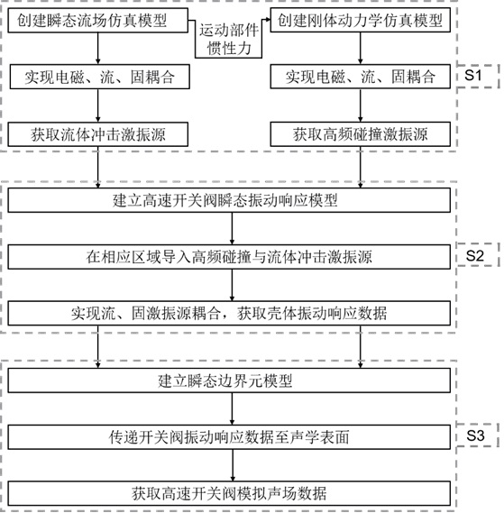
[0074] Such as figure 1 As shown, the high-speed switching valve simulation sound field modeling method coupled with high-frequency collision and fluid impact in this embodiment includes the following steps:

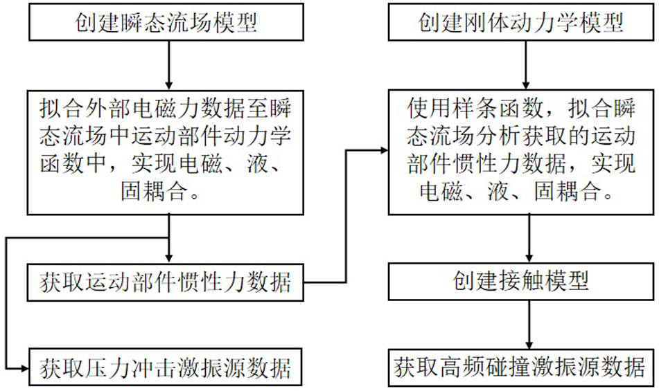
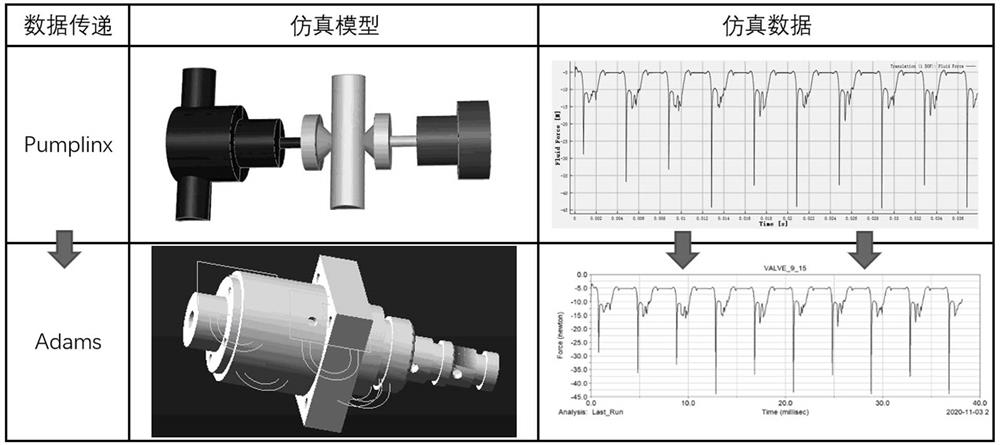
[0075] Step S1: First establish a transient flow field simulation model to obtain the fluid shock excitation source on the inner wall of the valve; then establish a rigid body dynamics simulation model and import the moving parts such as valve core and moving armature obtained in the transient flow field simulation model Inertial force data, to obtain high-frequency collision excitation source, the simulation steps are as follows figure 2 As shown, the specific process is:

[0076] Use SOLIDWORKS to establish a three-dimensional geometric model of the switch valve, import the model into Workbench Geometry, process the model with the help of the DesignModeler-Tools-Fill module, and export the flow field model;

[0077] Import the flow field model into the Pumplinx simu...


PUM


Abstract

The invention relates to a high-speed switch valve simulation sound field modeling method coupling high-frequency collision and fluid impact, which comprises the following steps: S1, performing electromagnetic, liquid and solid physical field coupling modeling through a high-speed switch valve; acquiring high-frequency collision excitation source data of a valve core and a valve seat as well as a moving armature and an iron core and fluid impact excitation source data of pressure impact and cavitation impact on the inner wall surface of a coupling valve body; S2, taking high-frequency collision and fluid impact excitation source data as input, analyzing a vibration transmission path, performing transient vibration response modeling of the high-speed switch valve, and obtaining surface vibration response data of a shell of the high-speed switch valve; S3, by means of the shell surface vibration response data, completing high-speed switch valve sound field modeling through a transient boundary element method, and obtaining high-speed switch valve sound field data. According to the method, electromagnetic, liquid and solid physical field coupling modeling of the high-speed switch valve is accurately achieved, fluid and mechanical excitation sources are comprehensively obtained and coupled, sound field data of the high-speed switch valve are rapidly and accurately predicted, and the research and development period of the high-speed switch valve is shortened.

Description

technical field [0001] The invention relates to a high-speed switch valve simulation sound field modeling method coupled with high-frequency collision and fluid shock. Background technique [0002] Microsecond-level high-speed switching valves have the characteristics of fast response and high control precision, and are widely used in important fields such as aerospace. Its working principle is to excite the moving armature through the electromagnet, and the moving armature, spring and other components act on the valve core together with the pressure oil, so that it produces high-frequency reversing action, realizes the alternate opening and closing of the valve port, and then achieves precise control of fuel flow. Purpose. However, high-frequency commutation leads to instantaneous changes in the kinetic energy of the oil, which will inevitably cause strong pressure shocks and cavitation shocks; and the high-frequency commutation between the valve core and the moving armatu...

Claims


Application Information

Patent Timeline
Patent Type & Authority Applications(China)
IPC IPC(8): G06F30/28G06F30/23G06F113/08G06F119/10G06F119/14
CPCG06F30/28G06F30/23G06F2113/08G06F2119/14G06F2119/10Y02T90/00
Inventor 陈晖刘文利黄惠李雨铮杜恒李启正生凯章
Owner FUZHOU UNIV
Learn More