High efficiency bottom filling method

A technology of underfill and underfill glue, which is applied in the direction of semiconductor/solid-state device parts, semiconductor devices, electrical components, etc., can solve the difficulty of meeting the requirements of flip-chip packaging, the decrease of flip-chip reliability, and the reduction of packaging reliability and other problems, to achieve the effects of efficiently controlling the overflow width and shape, increasing the motion rate, and filling with high precision

Pending Publication Date: 2021-04-09
WUHAN UNIV
View PDF4 Cites 3 Cited by
  • Summary
  • Abstract
  • Description
  • Claims
  • Application Information

AI Technical Summary

Problems solved by technology

[0004] However, there are also problems with the above-mentioned underfill method: pressure-driven underfill method-although it can be filled quickly, it is often accompanied by air bubbles in the underfill fluid, which reduces the reliability of the package, and requires a special mold, which is complex and costly. Higher; no-flow underfill method-although the process is simple, it is required that the filling fluid does not contain particles that affect reflow soldering, such as SiO2 particles, and the solder balls on the control chip are accurately placed on the pads of the substrate. Difficult; wafer-level underfill and molded underfill share these issues, both leading to reduced flip-chip reliability
[0005] It can be seen that the current underfill production process has been difficult to meet the requirements of flip-chip packaging. In order to meet the needs of the development of large-size, high-density flip-chip packaging, it is necessary to explore a new process for flip-chip underfill molding.

Method used


Image

  • High efficiency bottom filling method
  • High efficiency bottom filling method
  • High efficiency bottom filling method

Examples


Embodiment Construction

[0024] The present invention will be further described below in conjunction with the accompanying drawings and embodiments.

[0025] A high-efficiency underfill method, comprising the steps of:

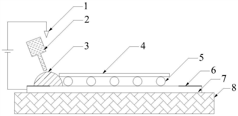
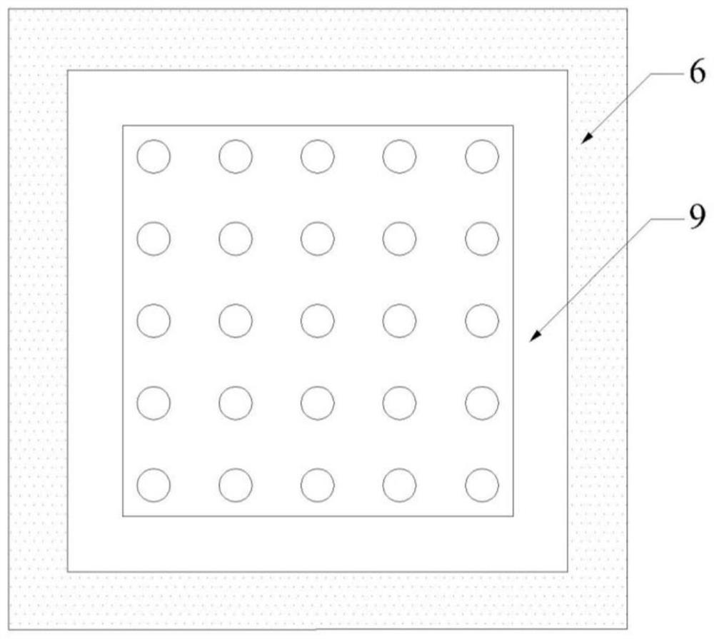
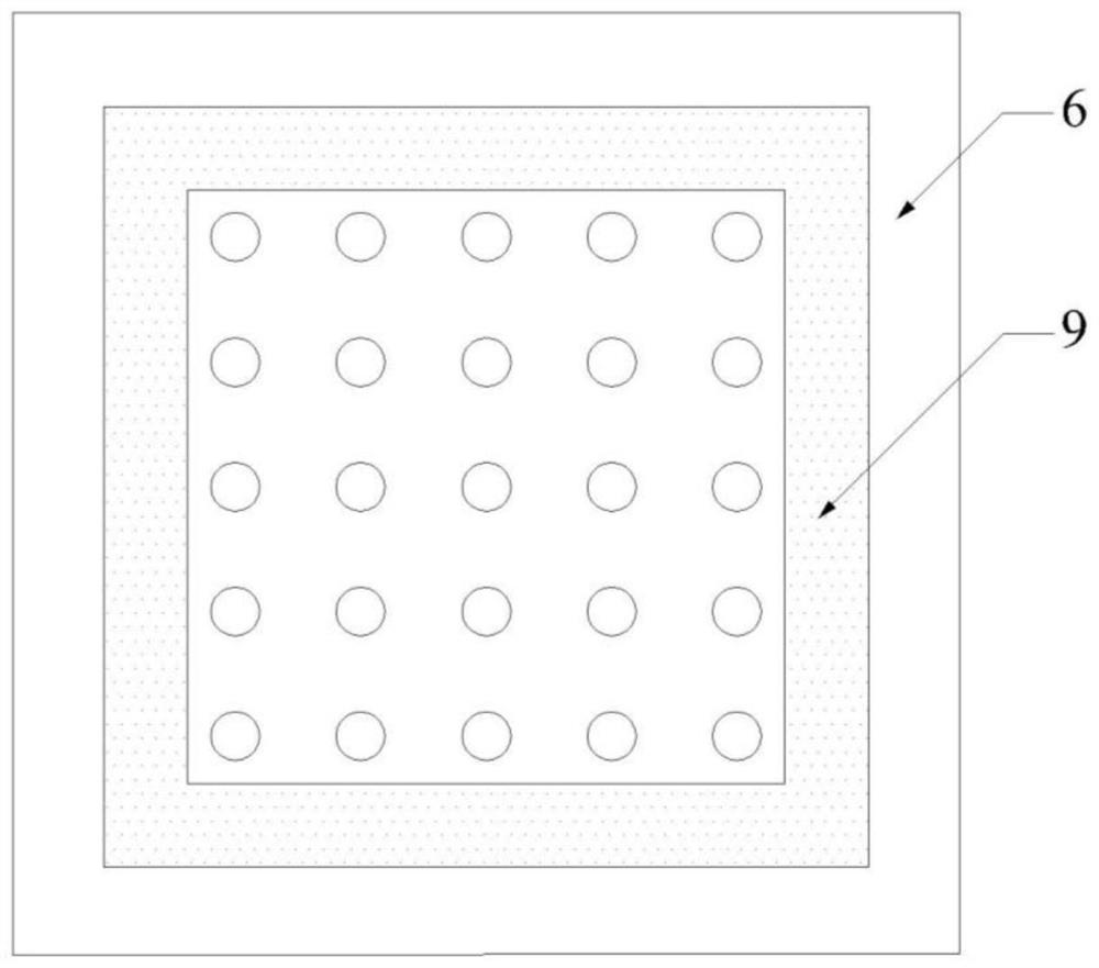
[0026] S1. Currently commonly used substrate materials include silicon, metal, ceramics, and composite materials. The basic types can be simply divided into conductive substrate 7 and insulating substrate. Before filling, for conductive substrate 7 (see figure 1 and figure 2 ), then make the insulating region 6 around the position away from the chip 4, for the insulating substrate (see image 3 ), then make the conductive region 9 around the position near the chip 4, the insulating region 6 and the conductive region 9 can be made by methods such as electroplating, coating, film sticking, photolithography, etc., preferably coating, the insulating region 6 and the conductive region 9 made The thickness is smaller than the filling gap, and the width is adjusted according to the overfl...


PUM


Abstract

The invention discloses a high-efficiency bottom filling method. The method comprises the following steps: S1, before filling, for a conductive substrate, manufacturing an insulating region at a position far away from a chip at a periphery, and for an insulating substrate, manufacturing a conductive region at a position close to the chip at the periphery; S2, during filling, using a glue dispenser to distribute a glue, starting a corona discharge device to generate ionic wind, using the ionic wind to continuously drive a bottom filling glue to spread, in a spreading process, preventing the bottom filling glue from flowing out of the filling region for the conductive substrate and the insulating region, and for the insulating substrate, using the ionic wind to directionally drive the bottom filling glue to move and spread out of the conductive region; and then enabling the filling region to be filled with the bottom filling glue under the action of a capillary force; and S3, after filling, closing the corona discharge device, and curing the bottom filling glue. The method is high in filling efficiency, high in filling precision, simple in process and low in cost.

Description

technical field [0001] The invention belongs to the technical field of electronic packaging, and in particular relates to a high-efficiency bottom filling method. Background technique [0002] As an important molding process of flip chip packaging, underfill directly affects the reliability of flip chip packaging. At present, the earliest and most widely used underfill method in industrialization is Capillary Pressure Driven Underfill (Capillary Pressure Driven Underfill) - using a syringe or a special glue dispenser to distribute the underfill fluid on one side (or multiple sides) of the chip, the effect of the fluid on the surface tension Slowly flow down and fill the gap between the chip and the substrate, and then put the chip and the substrate together in an oven for curing, so that the underfill material is bonded with the substrate, chip and solder balls. [0003] The capillary action in the capillary-driven underfill method has complexity and low controllability, re...

Claims


Application Information

Patent Timeline
Patent Type & Authority Applications(China)
IPC IPC(8): H01L21/56H01L23/31
CPCH01L21/563H01L23/3128
Inventor 郑怀刘洁苏振鹏刘胜
Owner WUHAN UNIV
Why Eureka
Try Eureka