Heat Flux Test Method for Attitude Control Engine in Vacuum Environment

A technology of heat flux density and vacuum environment, which is applied in the direction of machines/engines, rocket engine devices, mechanical equipment, etc., can solve problems such as unstable propellant supply, long vacuuming time, and large error in heat flux loading, so as to ensure constant heat flow Density requirements, extended service life, and the effect of precise loading

Active Publication Date: 2022-04-12
XIAN AEROSPACE PROPULSION TESTING TECHN INST
View PDF7 Cites 0 Cited by
  • Summary
  • Abstract
  • Description
  • Claims
  • Application Information

AI Technical Summary

Problems solved by technology

[0009] The present invention aims to solve the problem of long vacuuming time, high ambient humidity, large heat flux loading error, non-directional heat radiation, and poor cooling effect in the current attitude control engine in the thermal test of the heat flux in the environmental simulation test cabin. And the problem of unstable propellant supply, and provide a heat flux density heat test method in the vacuum environment of the attitude control engine

Method used


Image

  • Heat Flux Test Method for Attitude Control Engine in Vacuum Environment
  • Heat Flux Test Method for Attitude Control Engine in Vacuum Environment
  • Heat Flux Test Method for Attitude Control Engine in Vacuum Environment

Examples


Embodiment Construction

[0056] The technical solutions of the present invention will be clearly and completely described below in conjunction with the embodiments of the present invention and the accompanying drawings. Apparently, the described embodiments do not limit the present invention.

[0057] A kind of heat flux heat test method in the vacuum environment of attitude control engine in the present embodiment, comprises the following steps:

[0058] Step 1 Installation of thermal environment device

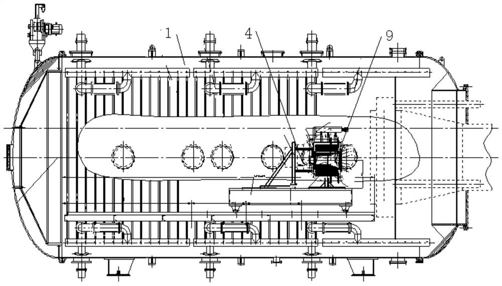
[0059] Step 1.1 as in figure 1 As shown, the attitude control engine simulation part 9 is installed in the vacuum chamber 1 through the fixed support frame 4; the attitude control engine simulation part 9 is divided into a body heat flow loading area and a nozzle tail heat flow loading area, and both heat flow loading areas are installed with The heating lamp array and the heat flow meter group; each heating lamp array is installed in the corresponding heat flow loading area through the lamp array ...


PUM


Abstract

The invention relates to a liquid rocket engine environment simulation test, in particular to a thermal test method for heat flux density in a vacuum environment of an attitude control engine, to solve the problem of the simulation test in the heat flux density heat test test of the existing attitude control engine in the environmental simulation test cabin. In the cabin, there are problems such as long vacuuming time, high ambient humidity, large error in heat flux loading, non-directional heat radiation, poor cooling effect and unstable propellant supply. The technical solution adopted in the present invention is: a thermal test method for heat flux density in a vacuum environment of an attitude control engine, comprising the following steps: step 1, installation of a thermal environment device; step 2, vacuumizing and cooling the vacuum chamber; Step 3. Calibrate the heat flux of the attitude control engine simulation part. Step 4. Replace the attitude control engine simulation part with the attitude control engine to be tested and install it in the vacuum chamber to conduct a thermal test on the heat flux density of the attitude control engine.

Description

technical field [0001] The invention relates to an environmental simulation test of a liquid rocket engine, in particular to a thermal test method for heat flux density in a vacuum environment of an attitude control engine. Background technique [0002] The 2000N thrust attitude control engine is the main power of an aircraft's orbit control cabin, and its performance and reliability need to be verified in complex environments such as heat tests in thermal vacuum coupling environments. At present, the attitude and orbit control power system only conducts individual test verification and assessment of mechanical environment, thermal environment, or thrust chamber heat test environment, and cannot carry out comprehensive test verification in real complex environments. Therefore, according to the test requirements, a 2000N attitude control engine is established at a height of 76km from the ground and a heat flux of 340kWm 2 The thermal test test simulates the high-altitude env...

Claims


Application Information

Patent Timeline
Patent Type & Authority Patents(China)
IPC IPC(8): F02K9/96
CPCF02K9/96
Inventor 李广会寇鑫秦永涛吕欣王冬党栋刘宇丰牛强吴飞飞任钰严岚张鹏王伟廖云鹏张腾飞
Owner XIAN AEROSPACE PROPULSION TESTING TECHN INST
Why Eureka
Try Eureka