
Screw rod supporting steel ball valve sleeve combined electromagnetic valve structure

A screw rod and solenoid valve technology, applied in the direction of multi-way valves, valve devices, valve details, etc., can solve the problems of large leakage, achieve the effects of reducing leakage, improving work reliability, and reducing processing accuracy

Active Publication Date: 2021-04-13
CHANGCHUN AVIATION HYDRAULIC CONTROL
View PDF10 Cites 0 Cited by
  • Summary
  • Abstract
  • Description
  • Claims
  • Application Information

AI Technical Summary

Problems solved by technology

[0003] In order to solve the problem that the existing electromagnetic valve structure achieves sealing under the joint action of spring force, electromagnetic force and hydraulic pressure, but there is a large leakage

Method used


Image

  • Screw rod supporting steel ball valve sleeve combined electromagnetic valve structure
  • Screw rod supporting steel ball valve sleeve combined electromagnetic valve structure

Examples


Embodiment Construction

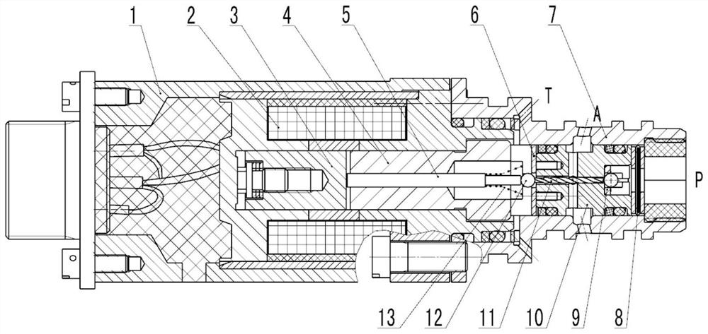
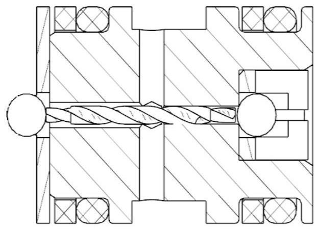
[0016] combine figure 1 and figure 2 Describe this embodiment, a screw-rod supporting steel ball valve sleeve combination solenoid valve structure, including an outer cover 1, an electromagnet assembly 2, an armature assembly 3, a stopper 4, a push rod 5, a left valve sleeve 6, a housing 7, and a filter screen Assembly 8, right valve sleeve 9, valve seat 10, screw rod 11, steel ball 12 and tower spring 13;

[0017] When the solenoid valve is energized, the armature assembly 3 overcomes the tower spring 13 to move to the right under the force of the electromagnet assembly 2 and engages with the stop iron 4, and closes the gap between the left steel ball and the left valve sleeve 6 under the action of the push rod 5 Open the passage between the right valve sleeve 9 and the right steel ball, and the fuel medium enters the control chamber of the screw rod 11 after being filtered by the filter assembly 8 from the P port, so that the A port and the P port are connected, and the A ...


PUM


Abstract

The invention discloses a screw rod supporting steel ball valve sleeve combined electromagnetic valve structure, and relates to the field of design of fuel oil electromagnetic valves (valves). The structure solves the problem that an existing electromagnetic valve structure realizes sealing under the combined action of spring force, electromagnetic force and hydraulic force but is large in leakage amount, the structure is composed of a screw rod assembly, a steel ball, an ejector rod, stop iron, an electromagnet assembly, a socket and an outer cover, when fuel oil flows in from a port P, under the action of the hydraulic force, the steel ball is pressed to a sealing hole opening of a valve body, the fuel oil flows into an inner cavity of the screw rod from a sealing gap to drive the screw rod to rotate, and the fuel oil flows into a port T along a spiral groove of the screw rod in the rotating process to form a suction negative pressure effect on a working port A, so that the zero leakage effect of the port A is achieved; and similarly, when a medium flows in from the port A, the zero leakage effect of the port T is achieved. According to the screw rod supporting steel ball combined electromagnetic valve structure, the purpose of reducing the leakage amount or avoiding leakage is achieved through rotation of the screw rod, and meanwhile the valve machining precision is reduced.

Description

technical field [0001] The invention relates to the field of fuel solenoid valve (valve) design, in particular to a novel solenoid valve structure type. Background technique [0002] The fuel solenoid valve (valve) solenoid valve is mainly used in the fuel control system of the aero-engine. During the design process of the fuel solenoid valve (valve), the leakage of the valve is an important indicator for evaluating the performance of the solenoid valve. Generally, the structure of the solenoid valve is mostly For flat or conical form. The seal is realized under the joint action of spring force, electromagnetic force and hydraulic pressure, but the leakage is relatively large. With the increase of the working time and frequency of the product, the leakage tends to increase, and the solenoid valve needs a large oil supply characteristic. It can only realize its conversion function, which has a great impact on the fuel supply of the system. Secondly, the previous valve struct...

Claims


Application Information

Patent Timeline
Patent Type & Authority Applications(China)
IPC IPC(8): F16K31/06F16K11/056B01D35/04F02C7/232
CPCF16K31/0637F16K11/056B01D35/046F02C7/232
Inventor 满春雷尹保明贾涛
Owner CHANGCHUN AVIATION HYDRAULIC CONTROL
Learn More