Two-column multi-cutter vertical machining center

A vertical machining center and two-column technology, which is applied in the direction of metal processing, metal processing equipment, metal processing machinery parts, etc., can solve the problems of poor levelness of beams and low cutting efficiency, and achieve resonance avoidance, efficiency improvement, and processing range wide effect

Inactive Publication Date: 2021-04-16
徐绍波
View PDF7 Cites 0 Cited by
  • Summary
  • Abstract
  • Description
  • Claims
  • Application Information

AI Technical Summary

Problems solved by technology

[0005] The purpose of the present invention is to provide a two-column multi-knife vertical machining center, which overcomes the deficiencies of the prior art, optimizes the beam structure, and adopts the center column to improve the rigidity of the equipment beam. One reverse setting is used to balance the rotating cutting force. It can combine five functions of gantry milling, gear milling machine, radial drill, vertical lathe and floor boring and milling in one, and solve large or extra-large vertical milling with a table diameter of more than 10 meters. The cutting efficiency of the lathe is low, and the problem of poor levelness of the beam of the ordinary double-column vertical lathe

Method used


Image

  • Two-column multi-cutter vertical machining center
  • Two-column multi-cutter vertical machining center
  • Two-column multi-cutter vertical machining center

Examples


Embodiment Construction

[0027] The following will clearly and completely describe the technical solutions in the embodiments of the present invention with reference to the accompanying drawings in the embodiments of the present invention. Obviously, the described embodiments are only some, not all, embodiments of the present invention. Based on the embodiments of the present invention, all other embodiments obtained by persons of ordinary skill in the art without making creative efforts belong to the protection scope of the present invention.

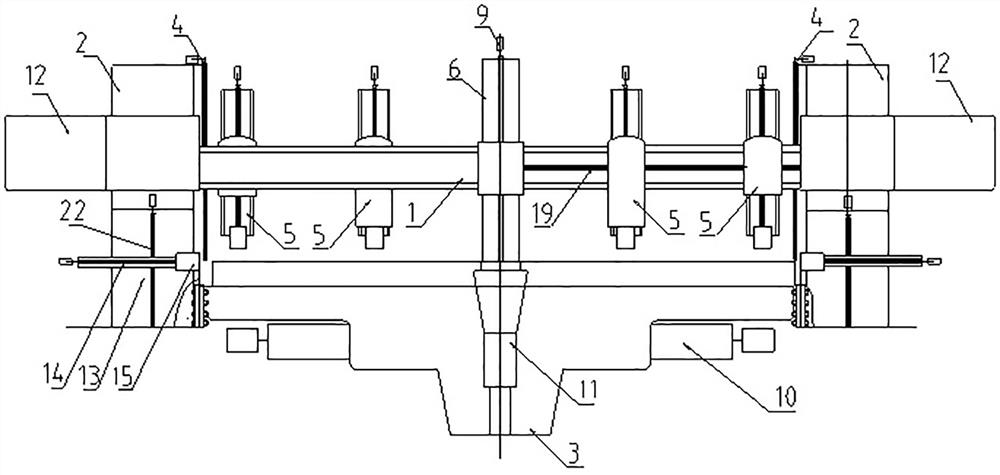
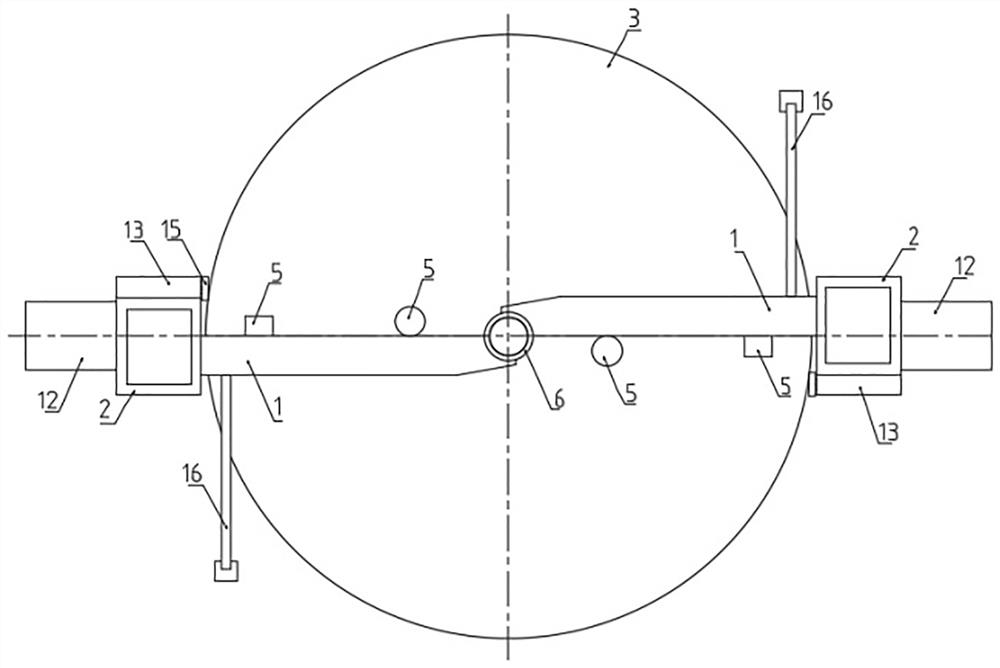
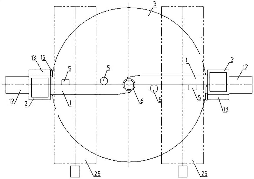
[0028] In the following embodiments, the vertical column lifting assembly 4, the boring and milling head 5, the main gearbox 10, the horizontal counterweight 12, the side tool rest 13, the side turret square ram 14, the auxiliary boring and milling head 15, the worm gear screw lifting Mechanism 18 and numerical control system are existing commercially available products. In the embodiment, the diameter of the workbench of this model is 10m.

[0029] See Fig...


PUM


Abstract

The invention relates to the field of vertical lathes, in particular to a two-column multi-cutter vertical machining center. The two-column multi-cutter vertical machining center comprises a cross beam, two stand columns and a workbench, and the two stand columns are arranged on the two sides of the workbench respectively. The cross beam is of a horizontally-arranged integrated structure, a middle column lifting assembly is arranged between the cross beam and a middle column, a stand column lifting assembly is arranged between the cross beam and the stand columns, the middle column lifting assembly and the stand column lifting assembly are synchronously controlled to achieve lifting movement of the cross beam, four boring and milling heads are arranged on the cross beam, and every two boring and milling heads are symmetrically distributed relative to the middle column. The lifting movement of the cross beam, the horizontal movement of each boring and milling head on the cross beam, the lifting movement of a square ram of a side tool rest and the rotation of the workbench are respectively controlled by a numerical control system. Compared with the prior art, the two-column multi-cutter vertical machining center has the following advantages that different tools and accessories are arranged, five functions of gantry boring and milling, a gear milling machine, a radial drill, a vertical lathe and floor type boring and milling can be achieved, the combined vertical lathe is efficient and multifunctional, and the machining efficiency is improved by multiple times.

Description

technical field [0001] The invention relates to the field of vertical lathes, in particular to a two-column multi-tool vertical machining center with optimized structure. Background technique [0002] The vertical lathe is referred to as "vertical lathe", and the vertical lathe is mainly used for processing large and heavy workpieces with large diameter and short length. The single-arm mobile vertical lathe originated in Europe more than 100 years ago. It is an economical, light-duty multifunctional lathe, and it has developed into a large and heavy-duty lathe. However, there are problems of uneven beams and resonance, which are world-wide problems. The beam of the super-large double-column vertical lathe can remain horizontal when it is still, but it will show concave deformation to varying degrees during cutting work (especially during powerful processing). It is the world's unsolvable problem. [0003] The Chinese utility model patent with the application number 2007200...

Claims


Application Information

Patent Timeline
Patent Type & Authority Applications(China)
IPC IPC(8): B23Q37/00B23Q1/01
Inventor 徐绍波徐玉荣徐蓓蓓尚英奇刘禹含
Owner 徐绍波
Why Eureka
Try Eureka