PVC floor film surface dust removal device

A technology of dust removal device and floor, which is applied in the direction of removing smoke and dust, cleaning method using gas flow, cleaning hollow objects, etc. The effect of increasing the dust removal area

Pending Publication Date: 2021-04-20
界首市鑫豪塑胶有限公司
View PDF8 Cites 0 Cited by
  • Summary
  • Abstract
  • Description
  • Claims
  • Application Information

AI Technical Summary

Problems solved by technology

[0006] PVC material can be used as the material of the floor film. During the production process, the surface of the floor film may be contaminated with dust, which will affect the product quality.

Method used


Image

  • PVC floor film surface dust removal device
  • PVC floor film surface dust removal device
  • PVC floor film surface dust removal device

Examples


Embodiment 1

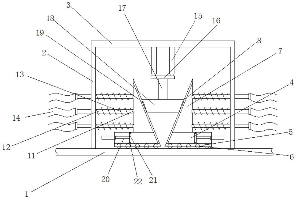
[0029] Embodiment 1: as Figure 1-5 As shown, a surface dust removal device for a PVC floor film includes a conveyor 1 and a dust collection bin 4. The dust collection bin 4 is provided with two groups, and the tops of both sides of the conveyor 1 are fixedly connected with brackets 2. A beam frame 3 is fixedly connected between the tops of the two groups of brackets 2;

[0030] The two groups of dust collection bins 4 are located above the conveyor 1, and both sides of the bottom of the two groups of dust collection bins 4 are fixedly equipped with mounting frames 5, and the mounting frames 5 of the two groups have built-in cavities. There are a number of dust suction rollers 6 that are rotatably connected between the inner walls of the mounting frame 5, and each set of the dust suction rollers 6 has a built-in cavity, and the side walls of each set of the dust suction rollers 6 are provided with a number of through holes 9. The first fan 10 is fixedly installed in the mount...

Embodiment 2

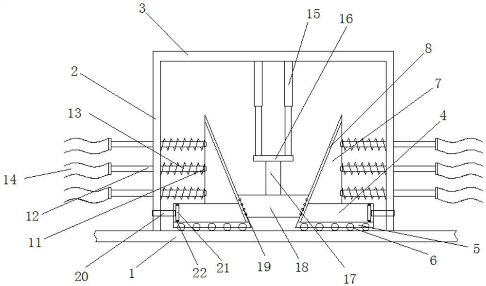
[0040] Embodiment 2: as Figure 1-5 As shown, a surface dust removal device for a PVC floor film includes a conveyor 1 and a dust collection bin 4. The dust collection bin 4 is provided with two groups, and the tops of both sides of the conveyor 1 are fixedly connected with brackets 2. A beam frame 3 is fixedly connected between the tops of the two groups of brackets 2;

[0041]The two groups of dust collection bins 4 are located above the conveyor 1, and both sides of the bottom of the two groups of dust collection bins 4 are fixedly equipped with mounting frames 5, and the mounting frames 5 of the two groups have built-in cavities. There are a number of dust suction rollers 6 that are rotatably connected between the inner walls of the mounting frame 5, and each set of the dust suction rollers 6 has a built-in cavity, and the side walls of each set of the dust suction rollers 6 are provided with a number of through holes 9. The first fan 10 is fixedly installed in the mounti...


PUM

PropertyMeasurementUnit
glass transition temperatureaaaaaaaaaa
tensile strengthaaaaaaaaaa
impact strengthaaaaaaaaaa

Abstract

The invention discloses a PVC floor film surface dust removal device. The PVC floor film surface dust removal device comprises a conveyor and two sets of dust absorption bins, supports are fixedly connected to the tops of the two sides of the conveyor, and a beam frame is fixedly connected between the tops of the two sets of supports. The two sets of dust absorption bins are located above the conveyor, mounting frames are fixedly mounted on the two sides of the bottoms of the two sets of dust absorption bins, cavities are formed in the two sets of mounting frames, a plurality of dust absorption rollers are rotationally connected between the inner walls of the two sets of mounting frames, a plurality of through holes are formed in the side wall of each set of dust absorption rollers, and first fans are fixedly mounted in the two sets of mounting frames. Dust collection bins are fixedly mounted at the tops of the two sets of dust absorption bins, the dust collection bins are arranged to be in a right triangle shape, and sliding rails are fixedly mounted on the inclined faces of the dust collection bins and the inner walls of the dust absorption bins. A PVC floor film can be repeatedly flattened, the attaching effect is guaranteed, dust absorption and dust removal effects are guaranteed, and collected dust can be treated in a centralized mode.

Description

Technical field: [0001] The invention relates to the field of PVC floor film production, in particular to a surface dust removal device for a PVC floor film. Background technique: [0002] Polyvinyl chloride, referred to as PVC (Polyvinyl chloride), is a vinyl chloride monomer (vinyl chloridemonomer, referred to as VCM) in peroxides, azo compounds and other initiators; or under the action of light and heat, it can be polymerized according to the mechanism of free radical polymerization. made polymer. Vinyl chloride homopolymers and vinyl chloride copolymers are collectively referred to as vinyl chloride resins. [0003] PVC is a white powder with an amorphous structure, the degree of branching is small, the relative density is about 1.4, the glass transition temperature is 77-90°C, it begins to decompose at about 170°C, and it has poor stability to light and heat. When exposed to sunlight, it will decompose to produce hydrogen chloride, and further autocatalyze the decompo...

Claims


Application Information

Patent Timeline
Patent Type & Authority Applications(China)
IPC IPC(8): B08B15/04B08B5/04B08B9/087B08B13/00B29C53/18
Inventor 肖殿飞黄继涛
Owner 界首市鑫豪塑胶有限公司
Why Eureka
Try Eureka