
New energy automobile motor main shaft connecting structure

A new energy vehicle and connection structure technology, which is applied in the direction of grinding frame, grinding drive device, grinding machine parts, etc. positioning and other issues

Inactive Publication Date: 2021-04-20
包科杰 +2
View PDF8 Cites 0 Cited by
  • Summary
  • Abstract
  • Description
  • Claims
  • Application Information

AI Technical Summary

Problems solved by technology

At present, the structure of the positioning component on the equipment that connects the motor shaft and the transmission shaft by welding is fixed, and the shaft body with different diameters cannot be positioned, so the scope of application is small; the smoke and odor gas during the welding process cannot be processed. The surrounding environment is polluted; after the two shafts are welded, the heat on them cannot be removed quickly (it needs to be transported to special cooling equipment for cooling treatment), resulting in long-term accumulation of heat on the two shafts, which may cause The misalignment caused by heat accumulation will reduce the accuracy of the shaft body and reduce the yield rate

Method used


Image

  • New energy automobile motor main shaft connecting structure
  • New energy automobile motor main shaft connecting structure
  • New energy automobile motor main shaft connecting structure

Examples


Embodiment Construction

[0025] The following will clearly and completely describe the technical solutions in the embodiments of the present invention with reference to the accompanying drawings in the embodiments of the present invention. Obviously, the described embodiments are only some, not all, embodiments of the present invention. Based on the embodiments of the present invention, all other embodiments obtained by persons of ordinary skill in the art without making creative efforts belong to the protection scope of the present invention.

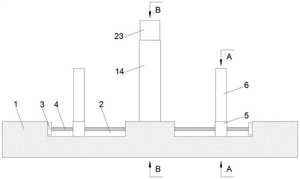
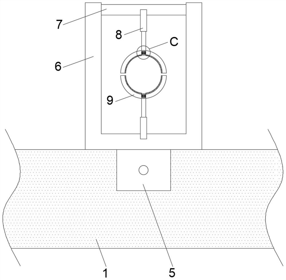
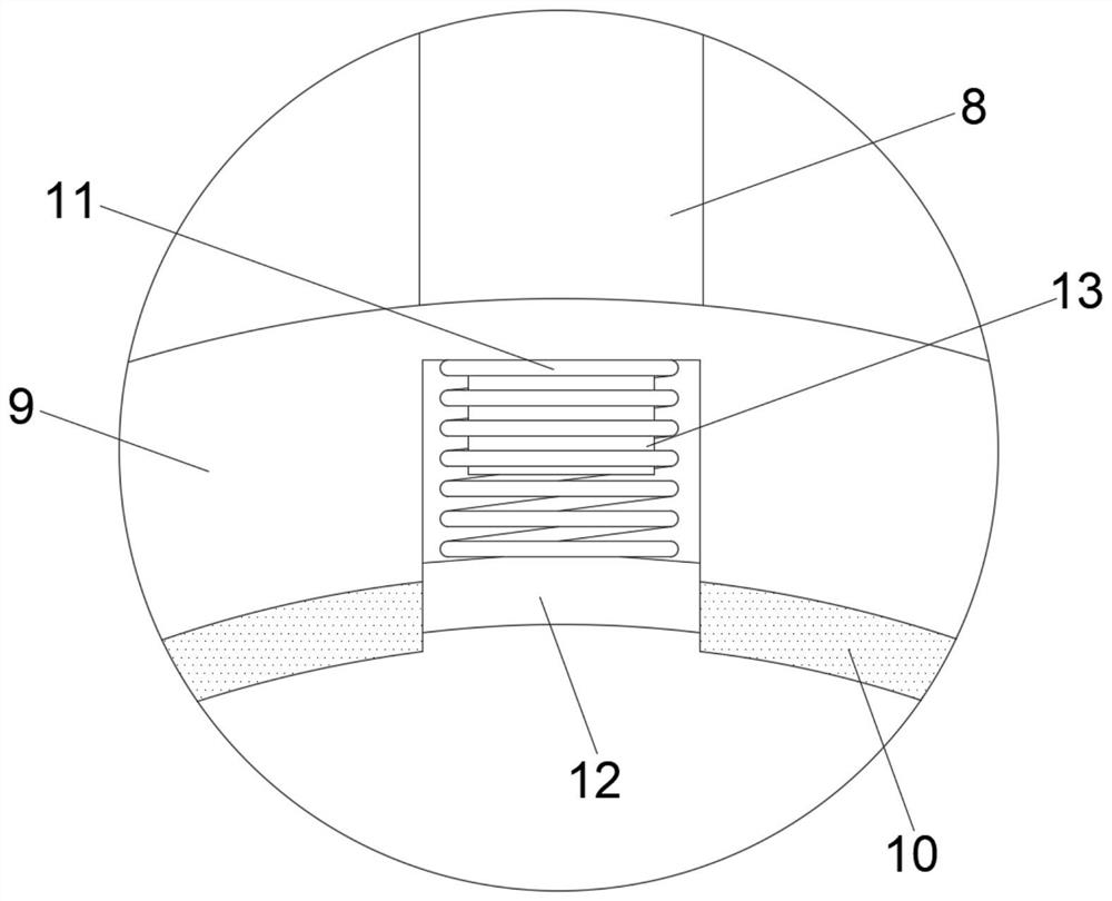
[0026] The present invention provides such Figure 1-6 The shown a new energy vehicle motor spindle connection structure includes a workbench 1, an adjustment mechanism on the workbench 1, a grinding mechanism, an air extraction mechanism and a cooling mechanism, wherein there are two adjustment mechanisms distributed in the working On both sides of the table 1, two moving slots 2 are symmetrically opened on both sides of the top wall of the workbench 1, and t...


PUM


Abstract

The invention discloses a new energy automobile motor main shaft connecting structure. The structure comprises a workbench, an adjusting mechanism, a polishing mechanism, an air exhaust mechanism and a cooling mechanism, wherein the adjusting mechanism, the polishing mechanism, the air exhaust mechanism and the cooling mechanism are arranged on the workbench, and the adjusting mechanism comprises a moving assembly and a positioning assembly; the polishing mechanism comprises a bearing seat arranged on the inner side of a storage rack and welded to the top wall of the workbench, a second electric push rod horizontally embedded inside the bearing seat, and an external frame welded to the end of the second electric push rod; and the air exhaust mechanism comprises a hard pipe obliquely penetrating through the storage rack and fixedly bonded to the storage rack, an absorption pipe head and a conveying hose, wherein the absorption pipe head and the conveying hose are connected to the two ends of the hard pipe correspondingly. According to the new energy automobile motor main shaft connecting structure, the upper side and the lower side of the outer wall of a shaft body are clamped in openings of two containing grooves, the shaft body cannot laterally slide on the inner sides of two clamping plates, the clamping plates and structures designed thereon are suitable for connection of two shaft bodies with different diameters, and the application range during actual machining is expanded.

Description

technical field [0001] The invention belongs to the technical field of new energy vehicles, and in particular relates to a connecting structure of a main shaft of a motor of a new energy vehicle. Background technique [0002] New energy vehicles refer to vehicles that use unconventional vehicle fuels as power sources, integrate advanced technologies in vehicle power control and drive, and form vehicles with advanced technical principles, new technologies, and new structures. New energy vehicles, also known as alternative fuel vehicles, include pure electric vehicles and fuel cell electric vehicles that all use non-petroleum fuels, as well as vehicles that partially use non-petroleum fuels such as hybrid electric vehicles and ethanol gasoline vehicles. All new energy vehicles that currently exist are included in this concept and are specifically divided into six categories: hybrid vehicles, pure electric vehicles, fuel cell vehicles, alcohol-ether fuel vehicles and natural ga...

Claims


Application Information

Patent Timeline
IPC IPC(8): B23P23/00B24B9/04B24B47/12B24B47/22B24B41/06B24B41/02B24B55/02B08B3/02
Inventor 包科杰
Owner 包科杰
Learn More