A high-efficiency shot blasting machine using electromagnetic drive

A technology of electromagnetic drive and shot blasting machine, which is applied in the field of polishing machines, can solve the problems of energy waste and poor processing effect, and achieve the effects of reducing consumption, improving practicability, and good polishing effect

Active Publication Date: 2022-02-18
盐城成越环保设备有限公司
View PDF15 Cites 0 Cited by
  • Summary
  • Abstract
  • Description
  • Claims
  • Application Information

AI Technical Summary

Problems solved by technology

[0004] The purpose of the present invention is to propose a high-efficiency shot blasting machine driven by electromagnetic force in order to solve the problem of poor processing effect of the existing shot blasting machine shot blasting method and certain energy waste.

Method used


Image

  • A high-efficiency shot blasting machine using electromagnetic drive
  • A high-efficiency shot blasting machine using electromagnetic drive
  • A high-efficiency shot blasting machine using electromagnetic drive

Examples


Embodiment 1

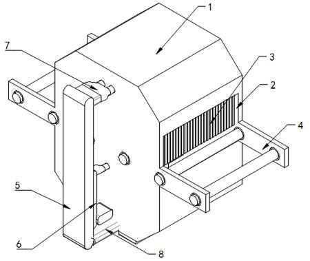
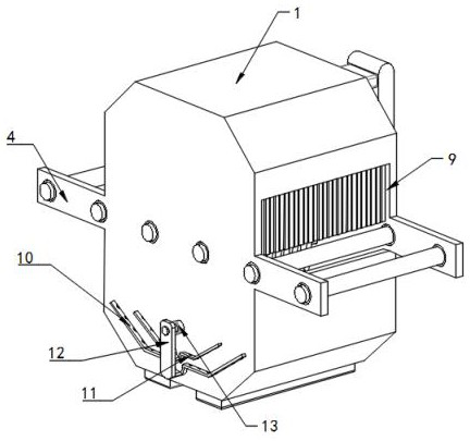
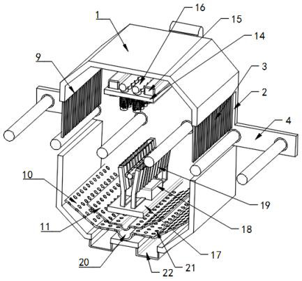
[0040] Example 1, please refer to Figure 1-8 , a high-efficiency shot blasting machine using electromagnetic drive, including a box body 1, the two sides of the box body 1 are respectively provided with a discharge port 2 and a material inlet 9, and there is a gap between the discharge port 2 and the material inlet 9 Conveyor table 4, and the discharge port 2 and the feed port 9 are provided with curtains 3, the inside of the box body 1 is respectively provided with an upper shot blasting mechanism 14 and a lower shot blasting mechanism 17, and the upper shot blasting mechanism 14 and the lower shot blasting mechanism Multiple shot blasting mechanisms 17 can be set, and the positions are staggered to ensure that they will not have a large impact on each other;

[0041] Two groups of shot blasting tubes 32 are fixedly connected to the upper blasting mechanism 14, and coils 33 are wound around the two groups of shot blasting tubes 32. There is a first capacitor 15, and the fir...

Embodiment 2

[0045] Example 2, please refer to Figure 1-8 , a high-efficiency shot blasting machine using electromagnetic drive, including a box body 1, the two sides of the box body 1 are respectively provided with a discharge port 2 and a material inlet 9, and there is a gap between the discharge port 2 and the material inlet 9 Conveyor table 4, and the discharge port 2 and the feed port 9 are provided with blinds 3, and the inside of the box body 1 is respectively provided with an upper shot blasting mechanism 14 and a lower shot blasting mechanism 17;

[0046] Two groups of shot blasting pipes 32 are fixedly connected on the upper shot blasting mechanism 14, and coils 33 are all wound on the two groups of shot blasting pipes 32, and a first capacitor 15 is arranged on the upper shot blasting mechanism 14, and the first capacitor 15 and The coils 33 are electrically connected, and the shot blasting tube 32 is communicated with a connecting tube 16;

[0047] The middle position of the ...


PUM


Abstract

The invention discloses a high-efficiency shot blasting machine driven by electromagnetic force, which includes a box body, and an upper shot blasting mechanism and a lower shot blasting mechanism are respectively arranged inside the box body; the upper shot blasting mechanism is fixedly connected with two A group of shot blasting tubes, and the two sets of shot blasting tubes are wound with energized coils, and the middle position of the lower shot blasting mechanism is fixedly connected with the first power transmission rod and the second power transmission rod, and the first power transmission rod and the second power transmission rod A shot blasting tube is fixedly connected between the transmission poles, and a push plate is slidingly embedded inside it. In the present invention, by installing an upper shot blasting mechanism and a lower shot blasting mechanism at the upper and lower ends of the box, the projectiles are ejected electromagnetically, by setting a plurality of shot blasting tubes on the upper shot blasting mechanism, and The mechanism is equipped with relatively independent shot blasting cylinders with internal shot blasting grooves, so that the movement of each projectile is relatively independent, which makes it easier to control, and then controls the strength of the shot blasting by controlling the size of the current, so as to obtain a better grinding effect.

Description

technical field [0001] The invention relates to the technical field of polishing machines, in particular to an electromagnetically driven high-efficiency shot blasting machine. Background technique [0002] Shot blasting machine refers to casting equipment that uses high-speed projectiles thrown by a shot blaster to clean or strengthen the surface of castings. The shot blasting machine can shake out sand, remove the core and clean the castings at the same time. In some areas, it is also called sand blasting machine and sand blasting machine. [0003] Most of the existing shot blasting machines use a motor to drive the shot blasting disc to rotate, and the shot blasting disc throws the projectiles that come out of the middle tube to the outside, so as to polish the objects. At the same time, the upward driving force of some projectiles cannot be well guaranteed, so that the projectiles do ineffective motion, waste energy, and reduce the effect of grinding processing. Therefo...

Claims


Application Information

Patent Timeline
Patent Type & Authority Patents(China)
IPC IPC(8): B24C3/00B24C5/08B24C9/00
Inventor 陈桂荣潘茜沈善普
Owner 盐城成越环保设备有限公司
Why Eureka
Try Eureka