Antenna synchronous mobile electronic tag read-write method and system

A technology of electronic tags and reading and writing methods, applied in electromagnetic radiation induction, record carriers used by machines, instruments, etc., can solve problems such as difficult to achieve reading and writing effects, difficult equipment debugging, and inability to use small jump distances, etc., to achieve Achieve miniaturization, increase productivity, and avoid cross-reading effects

Active Publication Date: 2021-04-20
KUNSHAN JETECH TECH CO LTD
View PDF3 Cites 1 Cited by
  • Summary
  • Abstract
  • Description
  • Claims
  • Application Information

AI Technical Summary

Problems solved by technology

Once the reading and writing application takes a long time, the time for reading and writing operations can only be gained by reducing the speed, thus losing the advantage of production capacity
Moreover, this continuous feeding mode cannot be used for products with a small jump distance (jump distance refers to the interval between labels appearing continuously on the backing paper, that is, the sum of the label length and spacing in the feeding direction)
In order to effectively shield, the smaller the jump distance of the tag, the smaller the effective reading and writing area of ​​the matched antenna, the smaller the allowable position deviation, the more difficult it is to debug the equipment, and it is often difficult to achieve the ideal reading and writing effect. Therefore, it is rarely used in practical applications

Method used


Image

  • Antenna synchronous mobile electronic tag read-write method and system
  • Antenna synchronous mobile electronic tag read-write method and system
  • Antenna synchronous mobile electronic tag read-write method and system

Examples


Embodiment 1

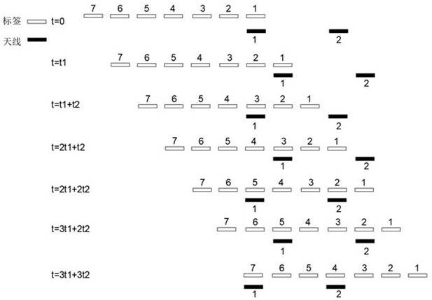
[0049] Such as figure 1 As shown, an antenna synchronous mobile electronic tag reading and writing system includes a label feeding line and two antennas beside the label feeding line.

[0050] The label feeding line is a straight line, and the labels are evenly spaced on the label feeding line. The jump distance of the label is P, and the reading and writing cycle of the label is set as T.

[0051] The two antennas are arranged along the label feeding direction, and the adjacent antennas are staggered by mq-1 hop distances, where q is a positive integer. In this example, the number of antennas is m=2, and if q=2, the adjacent antennas are staggered by 3 jump distances.

[0052] The reciprocating movement of the antenna is controlled by the mobile unit. When the antenna moves in the direction of material feeding, it remains relatively static with the corresponding label for reading and writing operations. When the antenna moves in the opposite direction of material feeding, it...

Embodiment 2

[0069] In this embodiment, on the basis of Embodiment 1, the reciprocating motion process of the antenna is further optimized.

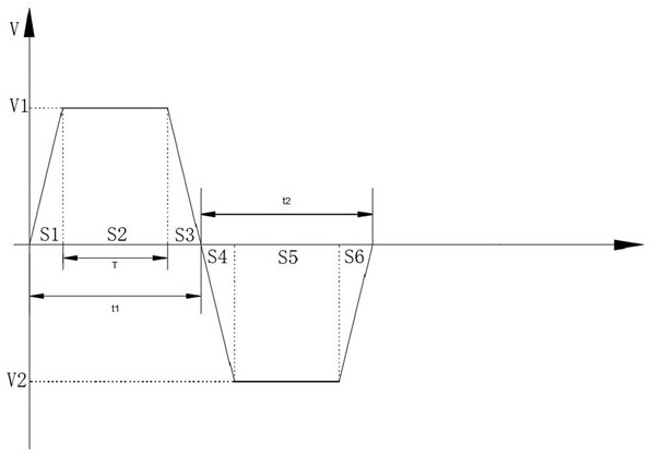
[0070] Such as image 3 Shown is the moving time-speed relationship diagram of the antenna. The movement of the antenna toward the feeding direction is divided into forward acceleration, uniform speed synchronization and forward deceleration in sequence. The speed V1 of uniform speed synchronization is the same as the feeding speed of the label feeding line. And the movement time of the uniform speed synchronization is T, and the antenna and the corresponding tag maintain a relatively static state for reading and writing operations during the uniform speed synchronization.

[0071] The movement of the antenna towards the opposite side of the feeding direction is divided into reverse acceleration, reverse constant speed and reverse deceleration in sequence, and the speed V2 of reverse uniform speed is greater than the speed V1 of uniform speed synchro...

Embodiment 3

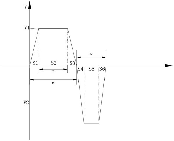
[0077] Such as Figure 4 As shown, this embodiment is basically the same as Embodiment 2. It also optimizes the reciprocating motion of the antenna, unevenly distributes the time for antenna read and write operations and the time for returning to the initial position. The difference is that this embodiment is configured with four antennas. With one reciprocating movement, the label feeding line moves 4 jumps.

[0078] The four antennas are arranged along the feeding direction, and the adjacent antennas are staggered by mq-1 jump distances, where q is a positive integer. In this example, the number of antennas is m=4, and if q=1, the adjacent antennas are staggered by 3 jump distances.

[0079] In order to facilitate understanding and visually display the data relationship, assuming the optimized reciprocating motion cycle t1+t2=2T, the feeding speed of the label feeding line is V=mP / (t1+t2)=4P / 2T.

[0080] In order to visually display the working process of this embodiment, ...


PUM


Abstract

The invention discloses an antenna synchronous movement electronic tag read-write method and system. The method comprises the steps: sequentially setting m antennas in a feeding direction, and enabling the antennas to be sequentially arranged according to a hop pitch sequence or enabling the adjacent antennas to be staggered by mq1 hop pitches; controlling the label feeding line to feed at a constant speed. Meanwhile, controlling the antenna to reciprocate, keeping the antenna in a static state relative to the corresponding label when the antenna moves towards the feeding direction to perform read-write operation, and controlling the antenna to move towards the direction opposite to the feeding direction and not to work in the process of returning to the initial position. The label feeding line is kept in a constant-speed feeding state all the time, the moving speed of the feeding line and the moving speed of the antenna can be adjusted, labels with different skip distances are matched, and the influence of the skip distances on the productivity is reduced to the minimum; under the condition of not changing the time required by reading and writing, the productivity can be improved by increasing the reading and writing antenna, the feeding speed and the antenna moving speed; and the antenna synchronously moves to prolong the retention time of the label in the effective read-write area, so that the shielding requirement required by label read-write is met, and the read-write reliability is improved.

Description

technical field [0001] The invention relates to the technical field of electronic tags, in particular to a method and system for reading and writing electronic tags with synchronous movement of antennas. Background technique [0002] Radio frequency tags, also known as electronic tags or RFID tags, are mainly composed of large-scale integrated circuit chips with identification codes and transceiver antennas. The power used is taken from the radio wave energy received by the transceiver antenna. It has the advantages of large capacity, long communication distance, difficult to copy, high tolerance to environmental changes, and the ability to read multiple tags at the same time. [0003] At present, the code writing operation in the production process of electronic tags is mainly carried out by roll-to-roll detection and coding machines. The existing roll-to-roll detection coding machine has two feeding modes: stepping and continuous. [0004] Among them, the step-feed mode ...

Claims


Application Information

Patent Timeline
Patent Type & Authority Applications(China)
IPC IPC(8): G06K7/10G06K19/077
Inventor 孙斌齐鸣
Owner KUNSHAN JETECH TECH CO LTD
Why Eureka
Try Eureka