
Intermediate-frequency transformer applied to power electronic transformer

A technology for power electronics and transformers, applied in the field of intermediate frequency transformers, can solve problems such as endangering personnel and equipment safety, insulating medium damage, system thermal damage, etc., and achieve the effects of improving safety, increasing withstand voltage level, and reducing temperature rise.

Inactive Publication Date: 2021-04-20
QINGDAO TOPSCOMM COMM
View PDF8 Cites 0 Cited by
  • Summary
  • Abstract
  • Description
  • Claims
  • Application Information

AI Technical Summary

Problems solved by technology

[0003] Power electronic transformers usually adopt a modular cascade topology, that is, a unit composed of a power module and an intermediate frequency transformer. The intermediate frequency transformer is a key device for energy conversion, and its stable operation is the basis for the stable and efficient operation of the power electronic transformer. Voltage system equipment requires a transformer with good insulation and withstand voltage and low partial discharge performance. At the same time, it needs a strong and practical connection system to ensure the effective work of the power module. At present, there are few such transformers that take into account both high withstand voltage and practical connection. System IF Transformer
[0004] In addition, due to the large voltage and current carried by the intermediate frequency transformer, the heating phenomenon is relatively serious, which can easily cause thermal damage to the system, and in severe cases, it will cause damage to the insulating medium, endangering the safety of personnel and equipment

Method used


Image

  • Intermediate-frequency transformer applied to power electronic transformer
  • Intermediate-frequency transformer applied to power electronic transformer
  • Intermediate-frequency transformer applied to power electronic transformer

Examples


Embodiment Construction

[0026]In order to make the objectives, technical solutions and advantages of the present invention, the present invention will be described in further detail below with reference to the accompanying drawings and examples. It will be appreciated that the specific embodiments described herein are intended to explain the present invention and is not limited thereto.

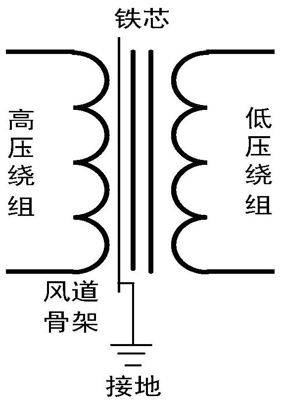
[0027]An intermediate frequency transformer applied to a power electron transformer, including a pour body, a low-voltage winding, a core assembly, and a connection assembly, and the connecting assembly secures the pour body, the low pressure winding, and the iron core assembly by screw fasteners to form an intermediate frequency transformer. Such asfigure 1 As shown, the wind bone frame is formed to form an equal potential body, which can effectively suppress the local discharge of the intermediate frequency transformer.

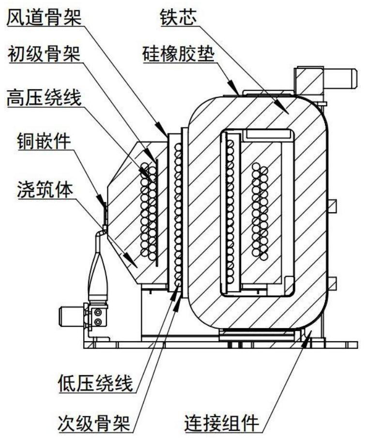
[0028]Such asfigure 2 As shown, an intermediate frequency transformer applied to a power electron transfo...


PUM


Abstract

The invention discloses an intermediate-frequency transformer applied to a power electronic transformer, which comprises a pouring body, a low-voltage winding, an iron core assembly and a connecting assembly, and is characterized in that the pouring body is used for improving the voltage withstanding level of the intermediate-frequency transformer, and mounting interfaces are reserved at the bottom and the top of the pouring body to realize overall reliable fixation; the low-voltage winding is used for receiving the electric energy converted by the high-voltage winding to obtain a required voltage level; the iron core assembly is used for forming a uniform magnetic circuit and realizing a voltage conversion function of the intermediate-frequency transformer; the connecting assembly is used for connecting the pouring body, the low-voltage winding and the iron core assembly, meanwhile, integral guide rail type installation of the medium-frequency transformer is achieved, and the batch assembly and maintenance work efficiency is improved; the transformer can effectively improve the withstand voltage, reduces the partial discharge, and solves problems that a transformer in the prior art is higher in temperature rise, is not convenient to fix, and is difficult to maintain.

Description

Technical field[0001]The present invention relates to the field of power systems, and more particularly to an intermediate frequency transformer applied to a power electron transformer.Background technique[0002]As the construction of intelligent grids continues to in-depth, the general amount of new energy technology is rapidly developed, and traditional transformers have disagreeable in response to emerging random impact resistance. As a new energy conversion device, the power electronics transformer is integrated including power electronics, power systems, computer, digital signal processing, automatic control theory, etc., which can achieve electrical isolation, power adjustment and intelligent control at the same time. All kinds of functions can better meet the construction needs of smart grids at this stage.[0003]Power electron transformers typically use a module-grade setup, that is, a unit of power module and an intermediate frequency transformer. The intermediate frequency t...

Claims


Application Information

Patent Timeline
Patent Type & Authority Applications(China)
IPC IPC(8): H01F27/32H01F27/22H01F27/36H01F27/30H01F27/26H01F27/08H01F27/29H01F27/06
Inventor 范建华徐鹏飞肖汝腾刘航王庆园李国富
Owner QINGDAO TOPSCOMM COMM
Features
  • Generate Ideas
  • Intellectual Property
  • Life Sciences
  • Materials
  • Tech Scout
  • Unparalleled Data Quality
  • Higher Quality Content
  • 60% Fewer Hallucinations
Learn More