Packaging structure and method of infrared thermal pile sensor

A packaging structure and packaging method technology, which is applied in the manufacture/processing of thermoelectric devices, the use of electric/magnetic devices to transfer sensing components, thermoelectric device components, etc., can solve the problems of large volume and complex process, and achieve integrated packaging. , the effect of shortening process steps and improving reliability

Pending Publication Date: 2021-04-20
NINGBO SEMICON INT CORP
View PDF0 Cites 1 Cited by
  • Summary
  • Abstract
  • Description
  • Claims
  • Application Information

AI Technical Summary

Problems solved by technology

[0004] However, in the existing infrared thermopile sensors, the thermopile unit and the thermosensitive unit are designed separately and then reassembled. The process is complex and the volume is large, which is contrary to the trend of miniaturization.

Method used


Image

  • Packaging structure and method of infrared thermal pile sensor
  • Packaging structure and method of infrared thermal pile sensor
  • Packaging structure and method of infrared thermal pile sensor

Examples


Embodiment 1

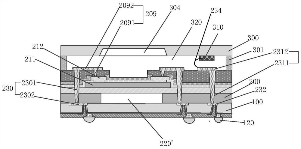
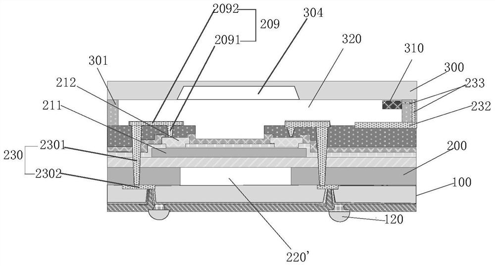
[0036] In order to solve the above problems, this embodiment provides a package structure of infrared thermal pile sensors, such as figure 1 shown, including:

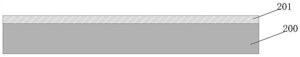
[0037] the first substrate 200;

[0038] A thermopile structure located on the first surface of the first substrate 200, the thermopile structure includes a thermopile body composed of at least one set of thermocouple pairs;

[0039] The cover substrate is arranged above the thermopile structure and forms a first cavity 320 with the upper surface of the thermopile structure. The film-like thermistor 310 is arranged on the cover substrate.

[0040] The cover substrate has a first surface and a second surface, the first surface is the surface where the cover substrate and the thermopile structure enclose the first cavity 320 , and the second surface is opposite to the first surface.

[0041] In this embodiment, the thermistor 310 is located on the first surface of the cover substrate; in one embodiment, the thermistor ...

Embodiment 2

[0082] This embodiment provides a method for packaging an infrared thermal pile sensor, including:

[0083] S01: providing a first substrate;

[0084] S02: forming a thermopile structure on the first surface of the first substrate, where the thermopile structure includes a thermopile body composed of at least one set of thermocouple pairs;

[0085] S03: forming a cover substrate on the upper surface of the thermopile structure, and connecting the cover substrate and the upper surface of the thermopile structure to form a first cavity;

[0086] S04: Forming a film thermistor on the cover substrate.

[0087] Step SON does not represent a sequence.

[0088] Figure 3 to Figure 11 It is a structural schematic diagram corresponding to the corresponding steps of the manufacturing method of a packaging structure of an infrared thermal pile sensor in this embodiment, refer to Figure 3 to Figure 11 , detailing the manufacturing method of the package structure of the infrared therm...


PUM


Abstract

The invention discloses a packaging structure and method of an infrared thermal pile sensor. The packaging structure comprises a first substrate, a thermopile structure and a sealing cover substrate, wherein the thermopile structure is positioned on the first surface of the first substrate and includes a thermopile main body consisting of at least one group of thermocouple pairs; and the sealing cover substrate is arranged above the thermopile structure, a first cavity is formed by the sealing cover substrate and the upper surface of the thermopile structure, and a film-shaped thermistor is arranged on the sealing cover substrate. The thermistor is arranged on the sealing cover substrate so that the thermopile structure and the thermistor can be formed in the same packaging structure at the same time, integrated packaging is achieved, the process steps are shortened, the size of the infrared thermopile sensor is reduced, and the reliability of the infrared thermopile sensor is improved.

Description

technical field [0001] The invention relates to the technical field of semiconductor packaging, in particular to a packaging structure and method for an infrared thermal pile sensor. Background technique [0002] Infrared thermal pile sensor (English name: transducer / sensor) is a detection device that detects information by transforming the sensed information into corresponding signal output according to certain rules. Typical infrared thermopile sensors, such as temperature infrared thermopile sensors, pressure infrared thermopile sensors, optical infrared thermopile sensors, etc., not only promote the transformation and upgrading of traditional industries, but also continue to develop new industries, becoming the focus of attention. [0003] With the rapid development of microelectromechanical systems (MEMS) technology, miniaturized infrared thermal pile sensors based on MEMS micromachining technology are widely used in temperature measurement, gas sensing, and optical ima...

Claims


Application Information

Patent Timeline
Patent Type & Authority Applications(China)
IPC IPC(8): H01L25/16H01L35/32H01L35/34H01L35/02H01L21/50G01J5/20G01J5/12G01J5/00G01D5/16G01D5/12
Inventor 韩凤芹
Owner NINGBO SEMICON INT CORP
Why Eureka
Try Eureka