Single-pole multi-throw switch with high harmonic suppression

A single-pole multi-throw switch, high-harmonic technology, applied in electronic switches, single-ended network, pulse technology and other directions, can solve problems such as harmonic interference, and achieve high harmonic suppression, low insertion loss, and low insertion loss. Effect

Active Publication Date: 2021-04-20
NO 55 INST CHINA ELECTRONIC SCI & TECHNOLOGYGROUP CO LTD
View PDF7 Cites 2 Cited by
  • Summary
  • Abstract
  • Description
  • Claims
  • Application Information

AI Technical Summary

Problems solved by technology

[0003] The present invention proposes a single-pole multi-throw switch with high harmonic suppression, and its purpose is to provide a single-pole multi-throw switch with high harmonic suppression for the above-mentioned deficiencies in the background technology, wit

Method used


Image

  • Single-pole multi-throw switch with high harmonic suppression
  • Single-pole multi-throw switch with high harmonic suppression
  • Single-pole multi-throw switch with high harmonic suppression

Examples


Embodiment 1

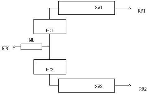
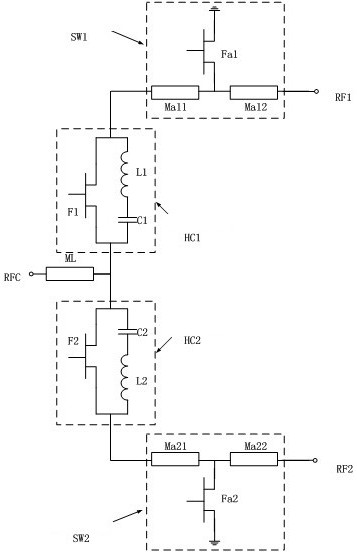
[0042] Such as figure 2 As shown, the high harmonic suppression switch is composed of radio frequency port RFC, radio frequency port RF1, radio frequency port RF2, transmission line ML, harmonic control circuit HC1, harmonic control circuit HC2, first switch arm SW1 and second switch arm SW2. One end of the transmission line ML is connected to the radio frequency port RFC, the other end is connected to the common end of the harmonic control circuit HC1 and the harmonic control circuit HC2, the other end of the harmonic control circuit HC1 is connected to one end of the first switch arm SW1, and the second end of the first switch arm SW1 The other end is connected to the radio frequency port RF1, the other end of the harmonic control circuit HC2 is connected to one end of the second switch arm SW2, and the other end of the second switch arm SW2 is connected to the radio frequency port RF2.

[0043] The harmonic control circuit HC1 includes a control die F1, an inductor L1 and ...

Embodiment 2

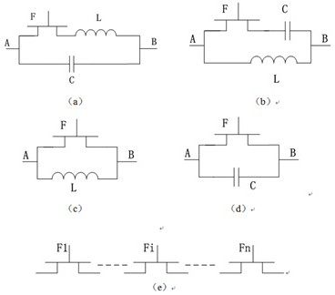
[0049] On the basis of Embodiment 1, the composition form of the harmonic control circuit HC, such as image 3 shown.

[0050] image 3 (a) The harmonic control circuit HC includes a control die F, an inductor L and a capacitor C. The control die F and the inductor L are connected in parallel with the capacitor C after being connected in series. The signal input port A and the signal output port B of the harmonic control circuit HC can be Interchange as needed for impedance.

[0051] image 3 (b) The harmonic control circuit HC includes a control die F, an inductor L and a capacitor C. The control die F and the capacitor C are connected in parallel with the inductor L after being connected in series. The signal input port A and the signal output port B of the harmonic control circuit HC can be Interchange as needed for impedance.

[0052] image 3 (c) The harmonic control circuit HC includes a control die F and an inductor L, and the control die F and the inductor L are c...

Embodiment 3

[0056] On the basis of Embodiment 1, the composition form of the switch arm SW, such as Figure 4 shown.

[0057] Figure 4 In (a), the switch arm SW is provided with the first transmission line Ma1 to the eighth transmission line Ma8 connected in series. The common end points of two adjacent transmission lines are also connected to one end of the control die Fa, so there are seven control dies Fa in total. The other end of each control die Fa is grounded.

[0058] Figure 4 There are also seven control dies Fa connected in series or in parallel between the first transmission line Ma1 to the eighth transmission line Ma8 in the middle switch arm SW. One end of the parallel-connected control die Fa is grounded, and the other end is connected to the common end of the two transmission lines. There are two output microstrip lines between two adjacent parallel control dies Fa, and a control die Fa is connected in series between these two transmission lines. The signal input po...


PUM


Abstract

The invention relates to a single-pole multi-throw switch with high harmonic suppression, relates to a radio frequency switch device, and belongs to the technical field of basic electrical elements. The high-harmonic suppression switch comprises an input transmission line with one end being an input end, the other end of the input transmission line is connected to one ends of a plurality of harmonic control circuits at the same time, the other end of each harmonic control circuit is connected to one end of a corresponding switch arm, and the other end of each switch arm is an output end. Each harmonic control circuit is composed of an inductor, a capacitor and a tube core, the phase of harmonic waves is changed by selecting proper inductors, capacitors and tube cores for series-parallel connection, and high harmonic suppression is achieved. On the basis of a single-pole double-throw switch, a plurality of harmonic control circuits and switch arms are added to form the single-pole multi-throw switch.

Description

technical field [0001] The invention is a single-pole multi-throw switch with high harmonic suppression, which belongs to the technical field of basic electrical components. Background technique [0002] In electronic communication systems, switches are widely used in radar systems, microwave communication systems and measurement systems, especially in transceiver components. The technical indicators of the switch mainly include: working frequency band, insertion loss, isolation, switching time, harmonic suppression, power capacity, etc., but the traditional switches have poor electrical performance indicators, mainly in: 1) low harmonic suppression; 2 ) Small power capacity; 3) Large area; 4) Large insertion loss, etc., which limits the wide application of such products in complex electromagnetic environments. Contents of the invention [0003] The present invention proposes a single-pole multi-throw switch with high harmonic suppression, and its purpose is to provide a ...

Claims


Application Information

Patent Timeline
IPC IPC(8): H03H5/00H03K17/687
Inventor 韩群飞陶洪琪陈庆余旭明王维波凌显宝
Owner NO 55 INST CHINA ELECTRONIC SCI & TECHNOLOGYGROUP CO LTD
Why Eureka
Try Eureka