Three-stage phase change heat exchanger

A technology of phase-change heat exchangers and heat exchangers, which is applied in the types of heat exchangers, indirect heat exchangers, heat storage equipment, etc., and can solve problems such as dryness, inability to transfer in time, and rising gas content of working fluids

Active Publication Date: 2021-04-23
BEIHANG UNIV
View PDF8 Cites 3 Cited by
  • Summary
  • Abstract
  • Description
  • Claims
  • Application Information

AI Technical Summary

Problems solved by technology

[0003] This single-structure heat exchanger can cope with the heat generated by high-power components during normal operation, but the heat generated by high-power components in a short period of high-frequency operation cannot be transferred in time, which can easily cause gas in the working fluid Rising rate leads to dry out, heat transfer capacity plummets

Method used


Image

  • Three-stage phase change heat exchanger
  • Three-stage phase change heat exchanger
  • Three-stage phase change heat exchanger

Examples


Embodiment 1

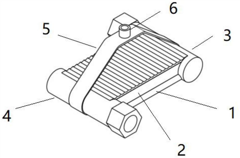
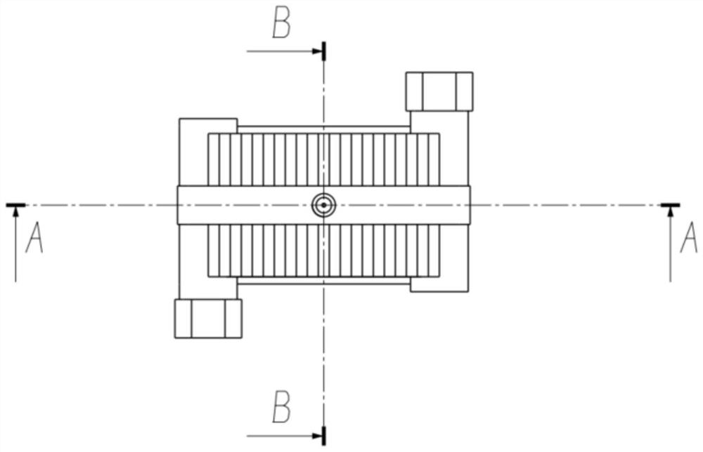
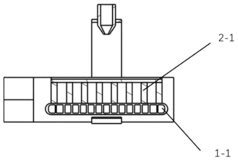
[0045] Such as Figure 4 As shown, the heat dissipation system for high-power components and parts according to an embodiment of the present invention includes a three-stage phase-change heat exchanger (1), high-power components and parts (2), a radiator (3), a liquid storage tank according to the present invention (4), fluorine pump (5), coolant supply system and connecting pipelines. According to a specific embodiment of the present invention, the phase-change material is selected as a phase-change metal material with a low melting point of 48°C, and is filled between the heat-conducting ribs (2-1). Driven by the fluorine pump, the refrigerant enters the three-stage phase-change heat exchanger, absorbs the heat released by the high-power components (2), changes from single-phase to gas-liquid two-phase, and then enters the radiator to dissipate heat, and the refrigerant returns to single-phase phase state, then enters the liquid storage tank, and is finally pumped away by t...

Embodiment 2

[0047] Such as Figure 5As shown, the heat dissipation system for high-power components and parts according to an embodiment of the present invention includes a three-stage phase-change heat exchanger (1), high-power components and parts (2), a radiator (3), a liquid storage tank according to the present invention (4), fluorine pump (5) coolant supply and recovery system (7) and connecting pipelines. According to a specific embodiment of the present invention, the phase-change material is selected as a phase-change metal material with a low melting point of 48°C, and is filled between the heat-conducting ribs (2-1). Driven by the fluorine pump, the refrigerant enters the three-stage phase-change heat exchanger, absorbs the heat released by the high-power components (2), changes from single-phase to gas-liquid two-phase, and then enters the radiator to dissipate heat, and the refrigerant returns to single-phase phase state, then enters the liquid storage tank, and is finally p...


PUM


Abstract

The invention discloses a three-stage phase change heat exchanger, and is used for heat dissipation of a high-power component with ultrahigh heat flux. The heat exchanger comprises a heat exchanger main body, a cooling liquid nozzle and a supporting structure of the cooling liquid nozzle, wherein the heat exchanger main body comprises a metal harmonica- shaped tube, a metal or alloy solid-liquid phase change material cavity, an expansion heat dissipation surface outside the cavity and two end heads; and the cooling liquid nozzle and the supporting structure thereof comprise a supporting structure and a nozzle or a nozzle array. A refrigerant fluid working medium flows into the metal harmonica-shaped tube through the end head and absorbs heat led in from the lower wall surface of the harmonica-shaped tube, and a vaporized refrigerant flows out from the other end head of the metal harmonica-shaped tube. When the heat production is drastically increased, the metal or alloy solid material in the cavity is subjected to solid-liquid phase change, meanwhile, the nozzle at the top sprays atomized cooling (insulating) liquid, and the atomized cooling (insulating) liquid is in contact with the upper surface of a heat dissipation shell and absorbs heat to be vaporized; and extra instantaneous large heat flow heat is absorbed through two phase change latent heat of metal or alloy solid-liquid phase change and cooling liquid spray liquid-gas phase change, and it is guaranteed that the temperature of a high-power component is maintained within a certain range to work normally.

Description

technical field [0001] The invention relates to a three-stage phase change heat exchanger. Background technique [0002] As the core components of electronic devices, high-power components show a rapid increase in heat flux density, which has reached 1000W / cm 2 level. At present, the heat dissipation method of high-power components mainly relies on air cooling, and liquid cooling and two-phase flow heat dissipation have also been promoted in recent years. Due to the limited heat dissipation capacity of air cooling, the current development has encountered a bottleneck. Liquid cooling and two-phase flow heat dissipation have the characteristics of strong heat dissipation capacity and small structural volume of the heat exchanger used, and have broad application prospects in the field of heat dissipation of high-power components. The overall structure of the radiators used in these two heat dissipation forms is basically similar. The working medium fluid flows through the se...

Claims


Application Information

Patent Timeline
Patent Type & Authority Applications(China)
IPC IPC(8): F28D20/02
CPCF28D20/021Y02E60/14
Inventor 袁卫星任柯先苗泽侯佳琪
Owner BEIHANG UNIV
Why Eureka
Try Eureka