Oil-cooled motor cooling system

A motor cooling and oil cooling technology, applied in the field of vehicles, can solve the problems of increasing the weight and cost of the gearbox, reducing the inlet temperature of the coolant, and the large volume of the water jacket, so as to avoid long-term accumulation, low inlet temperature and good cooling effect Effect

Active Publication Date: 2021-04-23
CHERY AUTOMOBILE CO LTD
View PDF4 Cites 11 Cited by
  • Summary
  • Abstract
  • Description
  • Claims
  • Application Information

AI Technical Summary

Problems solved by technology

[0003] Water-cooled drive motors need to be equipped with a water jacket to circulate the coolant in the water jacket, but this cooling method has the following disadvantages: 1) It can only cool the iron core, but the stator winding, which generates the most heat, cannot be directly cooled. Cooling, resulting in poor heat dissipation of the drive motor and low motor efficiency. To exert the same power, it is necessary to increase the flow rate of the coolant and reduce the inlet temperature of the coolant, thereby increasing the performance requirements for the oil cooler and the oil pump.
2) The water jacket generally needs to be press-fitted with the stator core. The interference fit is difficult and easy to heat unevenly, resulting in inconsistent deformation of the stator core, affecting the magnetic field generated by the motor, and then affecting the normal performance of the motor. to play
3) The volume of the water jacket is relatively large and heavy, which increases the overall weight and cost of the gearbox

Method used


Image

  • Oil-cooled motor cooling system
  • Oil-cooled motor cooling system
  • Oil-cooled motor cooling system

Examples


Embodiment Construction

[0065]In order to make the purpose, technical solutions and advantages of the present application, the present application will be further described in connection with the accompanying drawings, which will be apparent from the following examples, and not all of the embodiments. Based on the embodiments in the present application, all other embodiments obtained without making creative labor have not made creative labor premises.

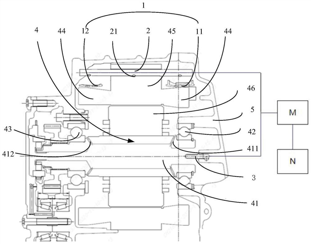
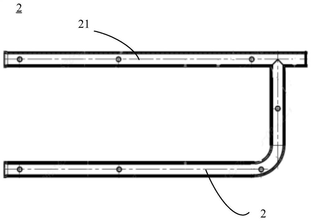
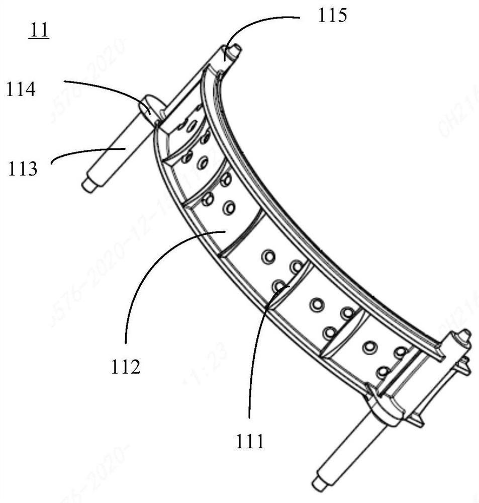
[0066]Such asfigure 1 As shown, the present application embodiment provides an oil-cooling motor cooling system including a gauge assembly 1, a fuel tube 2, a further oil tube 3, and a motor 4.

[0067]The motor 4 includes a rotor shaft 41 that supports a first bearing 42 and a second bearing 43 of the rotor shaft 41, a stator winding 44, a stator core 45, and a rotor core 46. It will be noted here that motor 4 can be a type of motor commonly seen in the art, so the positional relationship between the internal components and various components is well known to th...


PUM


Abstract

The invention discloses an oil-cooled motor cooling system. The system comprises an oil collecting assembly, an oil spraying pipe, an oil guiding pipe and a motor. A plurality of oil throwing holes are formed in a rotor shaft of the motor, and when the rotor rotates, cooling oil injected through the oil guide pipe is thrown and splashed to the inner sides of bearings on the two sides of the rotor shaft through the oil throwing holes in the rotor shaft and then rebounded to the inner side of a stator winding and a rotor iron core. A plurality of oil spraying holes are formed in the oil spraying pipe, so that cooling oil in the oil spraying pipe can be sprayed to the oil collecting assembly. The oil collecting assembly comprises a first oil collecting disc and a second oil collecting disc which are arc-shaped and provided with a plurality of through holes, and cooling oil in the oil collecting discs is dripped on the stator winding and the stator iron core through oil holes. According to the system, the oil collecting assembly, the oil spraying pipe and the oil guiding pipe which are simple in structure are utilized, cooling of the inner side and the outer side of the stator winding, the stator iron core, the rotor and the inner sides of the bearings on the two sides of the rotor shaft is achieved through the two oil cooling paths, the cooling range is wide, and the cooling effect is good.

Description

Technical field[0001]This application relates to the technical field of vehicle, and specific relates to an oil-cooling motor cooling system.Background technique[0002]Most pure electric cars or part of the mixed power vehicle is used by water-cooled drive motors.[0003]The water-cooled drive motor is required to provide a water jacket to cause the coolant to circulate in the water jacket, but this cooling method has the following disadvantages: 1) Cooling can only be cooled to the core, but the maximum stator winding of the heat generation cannot be directly Cooling, resulting in a low heat dissipation effect of the drive motor, the motor is less efficient, and the same power needs to increase the flow rate of the coolant and reduce the inlet temperature of the coolant, thereby increasing the performance requirements of the oil cooler and oil pump. 2) Water jackets generally need to match the stator core, and the extra-balance is more difficult and easy to heat uneven, resulting in i...

Claims


Application Information

Patent Timeline
Patent Type & Authority Applications(China)
IPC IPC(8): H02K9/19H02K7/00H02K7/08H02K5/20
CPCH02K9/19H02K7/003H02K7/083H02K5/20
Inventor 顾存行耿丽珍周之光李亚南
Owner CHERY AUTOMOBILE CO LTD
Why Eureka
Try Eureka