Supercharge Your Innovation With Domain-Expert AI Agents!

Permanent magnet synchronous motor control method based on sliding mode observer

A technology of permanent magnet synchronous motor and sliding mode observer, which is applied in the direction of motor generator control, AC motor control, electronic commutation motor control, etc., can solve problems such as large amount of calculation, poor robustness, and difficulty in realization, and achieve improved Estimate accuracy and reduce the effect of trembling array

Inactive Publication Date: 2021-04-23
SHANGHAI INST OF TECH
View PDF0 Cites 6 Cited by
  • Summary
  • Abstract
  • Description
  • Claims
  • Application Information

AI Technical Summary

Problems solved by technology

The model reference adaptive control method is very dependent on the motor parameters and has poor robustness
The Carr filter method uses the minimum variance estimation, which has a large amount of calculation and is not easy to implement

Method used


Image

  • Permanent magnet synchronous motor control method based on sliding mode observer
  • Permanent magnet synchronous motor control method based on sliding mode observer
  • Permanent magnet synchronous motor control method based on sliding mode observer

Examples


Embodiment Construction

[0062] The present invention will be described in detail below in conjunction with specific embodiments. The following examples will help those skilled in the art to further understand the present invention, but do not limit the present invention in any form. It should be noted that those skilled in the art can make several changes and improvements without departing from the concept of the present invention. These all belong to the protection scope of the present invention.

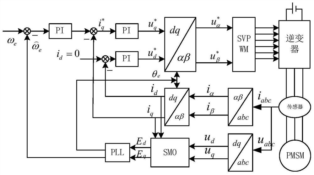
[0063] figure 1 The schematic diagram of the control principle of the permanent magnet synchronous motor based on the sliding mode observer provided by the embodiment of the present invention, such as figure 1 As shown, using i d = 0 control scheme, the direct axis current i d Feedback value, after PI adjustment, get the given value of direct axis voltage The deviation between the given speed and the estimated speed, after PI adjustment, the given value of the quadrature axis current is obtained a...


PUM


Abstract

The invention provides a permanent magnet synchronous motor control method based on a sliding mode observer. The method comprises the following steps: constructing a mathematical model of a permanent magnet synchronous motor under a synchronous rotating coordinate system and a sliding mode observer; using the sliding mode observer for estimating the current, defining a sliding mode surface function, and after the system enters a sliding mode, filtering out high-frequency signals in the back electromotive force through a low-pass filter to obtain an equivalent control quantity; establishing a motor three-phase stator winding end voltage equation, and obtaining a transformation matrix according to a synchronous rotation coordinate transformation principle; substituting the transformation matrix into a three-phase stator voltage equation to obtain a back electromotive force equation containing rotor information; and constructing a closed-loop PI regulator through a back electromotive force equation, and determining rotor position information of the permanent magnet synchronous motor according to the closed-loop PI regulator. Therefore, the problem of large error of angle estimation due to the existence of a jitter matrix in an arc tangent function is solved, the jitter matrix of sliding mode control can be reduced, and the estimation precision of the rotor position and the rotating speed is improved.

Description

technical field [0001] The invention relates to the technical field of motor control, in particular to a control method of a permanent magnet synchronous motor based on a sliding mode observer. Background technique [0002] With the application of rare earth cobalt and neodymium iron boron in the manufacture of permanent magnet materials, permanent magnet synchronous motors have gained huge development space. Permanent magnet synchronous motors are widely used in electric vehicles because of their simple structure and high power density. , aerospace, rail transit and other industrial fields. [0003] In the vector control of permanent magnet synchronous motors, traditional mechanical sensors such as photoelectric encoders are often used for speed identification. Installing the mechanical sensor will not only increase the volume of the motor, but also increase the manufacturing cost of the motor. Not only that, the mechanical sensor is easily affected by the ambient tempera...

Claims


Application Information

Patent Timeline
IPC IPC(8): H02P21/00H02P21/18H02P25/026
Inventor 宗剑闫永辉郭永馨姜豪李富雄董建功
Owner SHANGHAI INST OF TECH
Features
  • R&D
  • Intellectual Property
  • Life Sciences
  • Materials
  • Tech Scout
  • Unparalleled Data Quality
  • Higher Quality Content
  • 60% Fewer Hallucinations
Learn More