Negative-pressure vacuum packaging machine for packaging high-quality white carbon black

A technology of vacuum packaging machine and silica, which is applied in the direction of packaging, transportation and packaging, and the type of packaged items. It can solve the problems of reducing the one-time loading capacity of packaging bags and the inability to effectively discharge silica gas, so as to increase one-time loading. Quantity, simple structure, and the effect of reducing gas content

Pending Publication Date: 2021-04-27
蚌埠市万科硅材料科技有限公司
View PDF10 Cites 0 Cited by
  • Summary
  • Abstract
  • Description
  • Claims
  • Application Information

AI Technical Summary

Problems solved by technology

[0004] What the present invention aims to overcome is the existing high-quality white carbon black packaging machine. During the charging process, the white carbon black gas cannot be effectively discharged, which greatly reduces the one-time loading capacity of the packaging bag. The purpose is to provide a high-quality Negative pressure vacuum packaging machine for quality silica packaging

Method used


Image

  • Negative-pressure vacuum packaging machine for packaging high-quality white carbon black
  • Negative-pressure vacuum packaging machine for packaging high-quality white carbon black
  • Negative-pressure vacuum packaging machine for packaging high-quality white carbon black

Examples


Embodiment 1

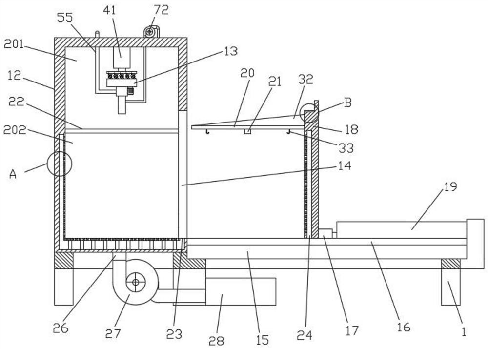
[0025] Such as Figure 1-3 Shown; a negative pressure vacuum packaging machine for high-quality white carbon black packaging, including:

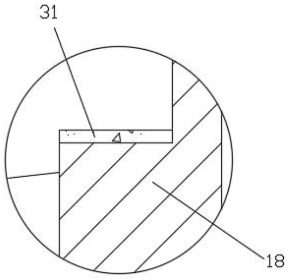
[0026] Device bracket 1, a sealing box 12 is installed on the device bracket 1, a material injection nozzle 13 is installed on the top of the sealing box 12, a feeding port 14 is provided on one side of the sealing box 12, and a feeding port 14 is installed on the device bracket 1 at the feeding port 14. Material conveying roller frame 15, discharge guide rail 16 is installed on the feed conveying roller frame 15, on the discharge guide rail 16, movable block 17 is slidably installed, hatch door 18 is installed on the movable block 17, and the discharge guide rail 16 is far away from the feed port A feeding push rod 19 is installed between one end of 14 and the hatch door 18, a support plate 20 is fixed on the hatch door 18, and a feed port 21 is provided on the support plate 20;

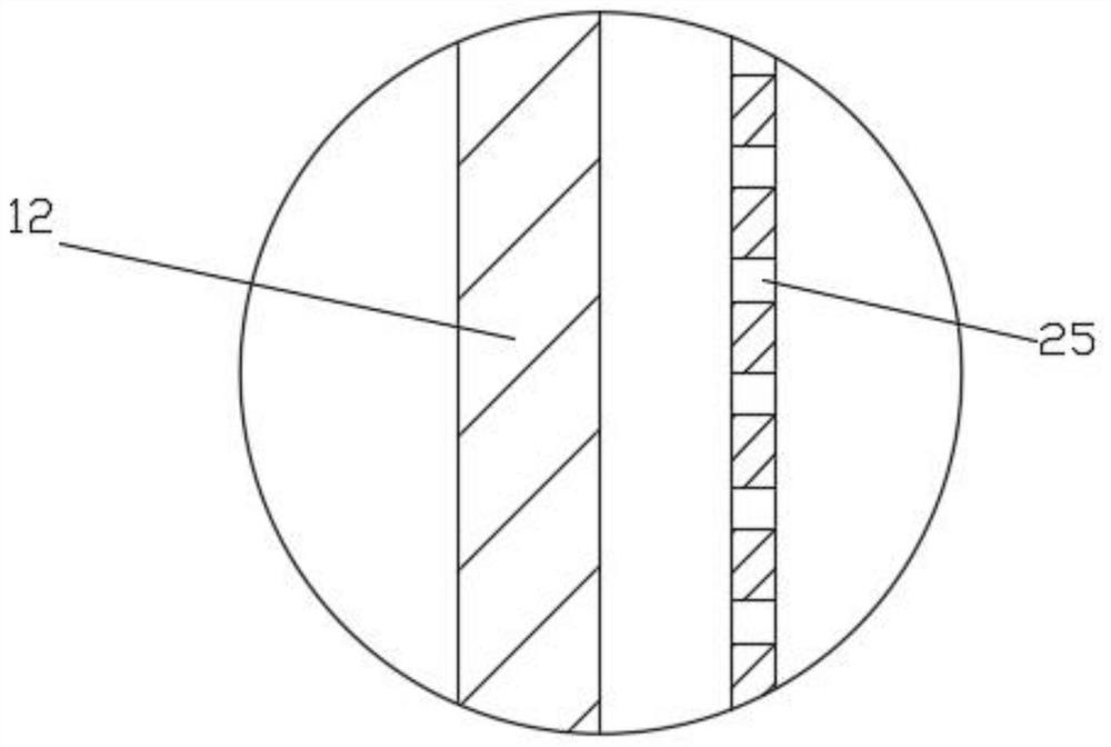
[0027] The inside of the sealing box 12 is provided with a...

Embodiment 2

[0033] On the basis of Example 1, such as figure 1 , image 3 As shown; the existing injection nozzle 13 is easy to cause the internal blockage of the nozzle during the injection process. In order to prevent the above problems, a telescopic push rod 41 is installed inside the injection bin 201, and the output end of the telescopic push rod 41 is installed with an intermediate The plate 42, the lower part of the middle plate 42 is fixed with a support spring 43, the injection nozzle 13 is installed on the support spring 43, and the injection nozzle 13 includes a housing 51 and a feeding rod 52;

[0034] The upper part of the housing 51 is equipped with a driving box 53, and the lower part of the housing 51 is equipped with an injection pipe 54. The injection pipe 54 communicates with the housing 51, and the side of the housing 51 is connected with a material pipe 55; the feeding rod 52 is arranged on the injection pipe. 54 inside, the feeding rod 52 passes through the drive bo...

Embodiment 3

[0038] On the basis of Example 2, such as Figure 1-5 Shown; After the material injection nozzle 13 completes the material injection, its end is extracted from the packaging bag, and part of the powder will be brought out at the end, which will easily cause dust and waste of the powder. The limit sleeve 71, the diameter of the injection pipe 54 is larger than the diameter of the limit sleeve 71, the side wall of the injection pipe 54 is a hollow structure, and the hollow structure in the side wall of the injection pipe 54 is connected to the air inlet of the auxiliary fan 72 through a pipeline , the air outlet of the auxiliary fan 72 is connected to the bag filter 28, and the lower end of the injection pipe 54 is provided with a suction hole 73.

[0039] There is a sealing ring 74 on the side ring of the outer ring of the limit sleeve 71 , and the outer diameter of the sealing ring 74 is equal to the inner diameter of the injection pipe 54 .

[0040] When injecting material, ...


PUM


Abstract

The invention discloses a negative-pressure vacuum packaging machine for packaging high-quality white carbon black. The machine comprises a device support, a sealing box and a cabin door, wherein a material injection spray head is installed on the upper portion of the sealing box, a supporting plate is fixed to the cabin door, and a material injection opening is formed in the supporting plate; and a bag opening of a packaging bag sleeves the material injection opening in the upper part of the supporting plate, and a feeding push rod is used for pushing the cabin door to move towards one side of a feeding port, so that a communicating hole in the lower end of the cabin door is in butt joint with an air guide hole in a charging cabin, after butt joint is completed, an exhaust fan is started to exhaust air out of the charging cabin, so that the interior of the charging cabin is in a negative pressure state, The material injection spray head injects the high-quality white carbon black into the packaging bag from the material injection opening, after the high-quality white carbon black enters the packaging bag, gas contained in the high-quality white carbon black can penetrate through the packaging bag and is exhausted into a bag-type dust collector through the cabin door and through holes in the charging cabin under the suction action of the exhaust fan, the gas content in powder loaded in the packaging bag is greatly reduced, and the one-time loading capacity of the packaging bag is increased.

Description

technical field [0001] The invention relates to the field of high-quality white carbon black packaging equipment, in particular to a negative pressure vacuum packaging machine for high-quality white carbon black packaging. Background technique [0002] High-quality white carbon black is a general term for white powdery X-ray amorphous silicic acid and silicate products, mainly referring to precipitated silica, fumed silica and ultrafine silica gel, also including powdered synthetic Aluminum silicate and calcium silicate etc. Silica is a porous substance, and its composition can be represented by SiO2 nH2O, where nH2O exists in the form of surface hydroxyl groups. Soluble in caustic alkali and hydrofluoric acid, insoluble in water, solvents and acids (except hydrofluoric acid). High temperature resistance, non-combustible, tasteless, odorless, with good electrical insulation. [0003] Due to the fine particle size of high-quality silica, the gas contained in these powders ...

Claims


Application Information

Patent Timeline
Patent Type & Authority Applications(China)
IPC IPC(8): B65B1/28B65B1/16B65B43/54
CPCB65B1/28B65B1/16B65B43/54
Inventor 陈君华杨万科周丽李启明郭雨杨妍杨河
Owner 蚌埠市万科硅材料科技有限公司
Why Eureka
Try Eureka