
Vertical vibration detection device

A vibration detection, vertical technology, applied in measuring devices, using electrical devices, measuring ultrasonic/sonic/infrasonic waves, etc., can solve problems such as narrow frequency range and dynamic range, affecting detection results, and electromagnetic field interference.

Active Publication Date: 2021-04-27
CHONGQING UNIV OF TECH
View PDF20 Cites 4 Cited by
  • Summary
  • Abstract
  • Description
  • Claims
  • Application Information

AI Technical Summary

Problems solved by technology

The electric measurement method is to convert the vibration of the measured object into electric quantity, and then measure it with electric quantity testing equipment. This method has high sensitivity, wide frequency range, dynamic and linear range, and is convenient for analysis and remote measurement, but it is easily affected by electromagnetic field interference. The mechanical method is to use the principle of leverage to amplify the vibration and record it directly. This detection method has strong anti-interference ability, but the frequency range and dynamic range are narrow, and a certain load will be added to the workpiece during detection, which will affect the detection result. It is mainly used for the measurement of low-frequency and large-scale vibration; according to the comparison of the main measurement methods, the electrical measurement method is still the most widely used method at present

Method used


Image

  • Vertical vibration detection device

Examples


Embodiment Construction

[0024] Embodiments of the present invention are described in detail below, examples of which are shown in the drawings, wherein the same or similar reference numerals designate the same or similar elements or elements having the same or similar functions throughout. The embodiments described below by referring to the figures are exemplary only for explaining the present invention and should not be construed as limiting the present invention.

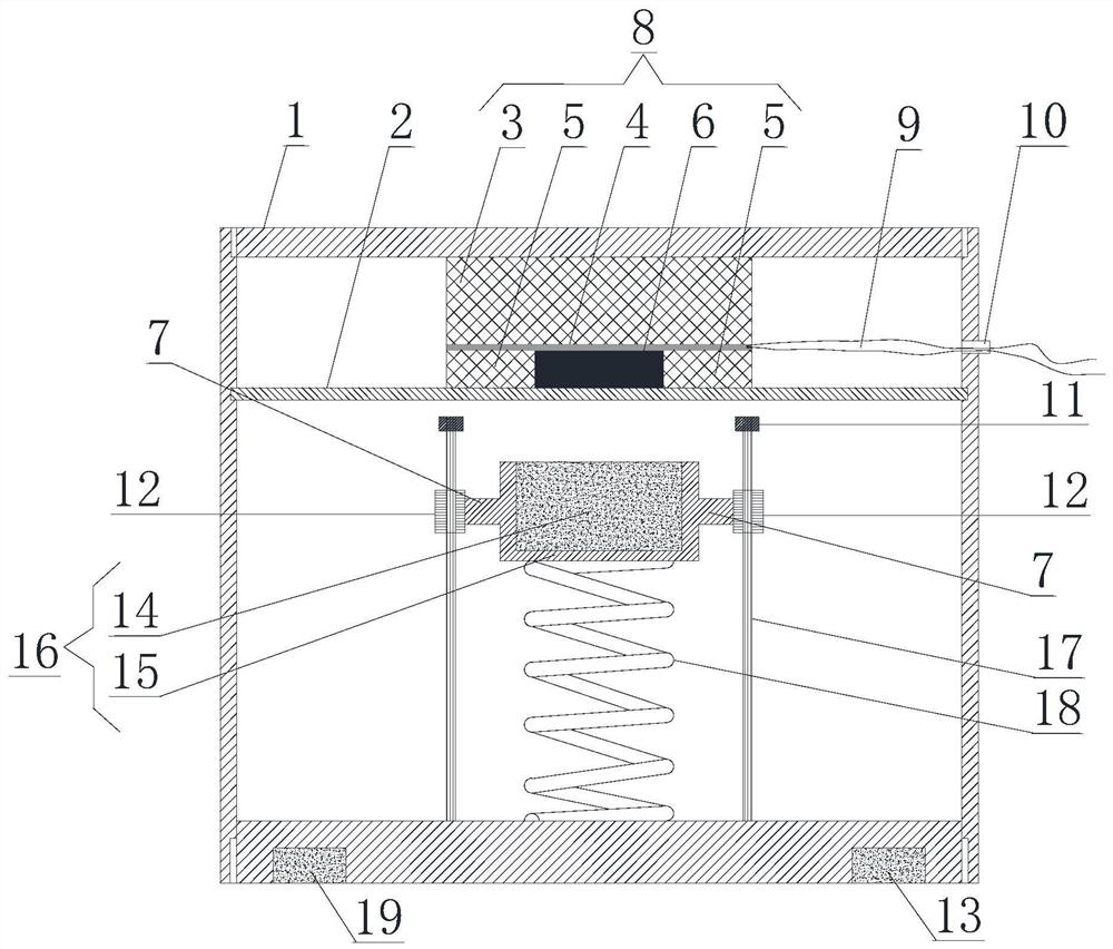
[0025] Such as figure 1 As shown, a vertical vibration detection device includes a housing 1. A partition 2 is arranged on the upper side of the housing 1. The upper part of the partition 2 is the sensing area, and the lower part of the partition 2 is the vibration area. A sensing component 8 is arranged in the sensing area, and the sensing component 8 includes three layers arranged from top to bottom. The first layer is the first rubber block 3 , the second layer is the resistance strain gauge 4 , and the third layer includes the magne...


PUM


Abstract

The invention provides a vertical vibration detection device which comprises a shell. A partition plate is transversely arranged at the upper portion in the shell, an induction area is arranged above the partition plate, a vibration area is arranged below the partition plate, an induction assembly is arranged in the induction area, the induction assembly comprises three layers arranged from top to bottom, the first layer is a first rubber block, the second layer is a resistance strain gauge, the third layer comprises a magnetic control elastic body and second rubber blocks located on the left side and the right side of the magnetic control elastic body respectively, the first rubber blocks, the resistance strain gauges, the second rubber blocks and the magnetic control elastic body are tightly installed together, leads are arranged on the resistance strain gauges, and the tail ends of the leads penetrate through wiring holes in the shell and are led out of the shell; a magnetic vibration mass block located under the magnetic control elastic body is arranged in the vibration area, a spring is connected between the bottom of the magnetic vibration mass block and the bottom of the shell, and guide mechanisms are vertically arranged on the two sides of the magnetic vibration mass block so that the magnetic vibration mass block can only vibrate vertically. And the vertical vibration of the object can be accurately detected.

Description

technical field [0001] The invention relates to the technical field of vibration detection, in particular to a vertical vibration detection device. Background technique [0002] According to the statistics of relevant departments, 80% of structural damage is fatigue damage caused by long-term vibration. This kind of vibration fatigue damage often causes great harm. In history, there have been large-scale airliners that were destroyed due to a bolt due to vibration fatigue fracture. Accidents involving human fatalities, the rotor of a large turbogenerator unit was broken into several sections due to bearing vibration fatigue, the Tacoma Bridge in the United States was broken due to wind vibration, and there are countless cases of heavy losses caused by vibration in engineering. In addition, when the vibration exceeds a certain limit, it will destroy the harmonious relationship between people and the environment, between people and machines, and damage human health. Therefore...

Claims


Application Information

Patent Timeline
IPC IPC(8): G01H11/06
CPCG01H11/06Y02E10/72
Inventor 米曾真居本祥
Owner CHONGQING UNIV OF TECH
Learn More