SFM point cloud correction method based on vector rotation of ned coordinate system
A calibration method and coordinate system technology, applied in measurement devices, 3D modeling, photo interpretation, etc., can solve problems such as complex processes, and achieve the effect of simplifying operation processes, reducing work intensity and equipment costs, and reducing safety risks.
- Summary
- Abstract
- Description
- Claims
- Application Information
AI Technical Summary
Problems solved by technology
Method used
Image
Examples
Embodiment 1
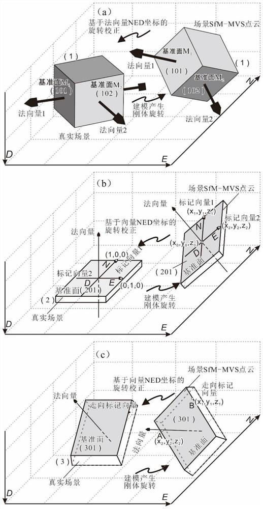
[0043] When the reference object set in the step S2 is an object, the reference plane is the reference plane M1 and the reference plane M2 on which the object is set, the reference plane M1 and the reference plane M2 intersect, and according to the inclination and inclination of the reference plane M1, the The object rotates around the normal vector of the surface until the attitude of the surface is correct, and then the inclination and inclination of the reference plane M2 are used to constrain the posture of the object to make the posture of the object correct. The normal vector NED coordinates of the reference plane M1 and the reference plane M2 are respectively (x1, y1, z1), (x2, y2, z2).
[0044] Such as figure 1 In (a), select two non-parallel surfaces arbitrarily, first rotate the shape (ie, inclination and inclination) of the datum plane M1 until the attitude of the plane is correct, and then the model of the datum plane M1 rotates around the normal vector of the plan...
Embodiment 2
[0061] When the reference object set in the step S2 is a horizontal datum plane, its shape is light and thin, and the reference auxiliary line is a marker vector 1 and a marker vector 2 intersected on the surface of the horizontal datum plane, and the marker vector 1 and the NED coordinate The N axes are consistent, the three-axis coordinates N=1, E=0, and D=0 of the mark vector 1 are denoted as (1, 0, 0), and the mark vector 2 is consistent with the E axis in the NED coordinates, so The three-axis coordinates N=0, E=1, and D=0 of the above-mentioned mark vector 2 are denoted as (0,1,0), and the NED coordinates of the normal vector of the horizontal datum plane are placed at (0,0,1), so The NED coordinates of the normal vector of the horizontal datum plane are (x0, y0, z0).
[0062] This embodiment is a variant of Embodiment 1, which is more simplified and only needs one horizontal plane. The additional condition is that a marker vector 1 and a marker vector 2 are drawn on the...
Embodiment 3
[0072] When the reference object set in the step S2 is an inclined datum plane, its shape is frivolous, and the reference auxiliary line is the direction marker vector and the normal vector set on the inclined reference plane, and the coordinates of the direction marker vector are measured by a compass, which is a Variables for arbitrary coordinates. After conversion, it is denoted as (x'1, y'1, z'1), and its normal vector NED coordinates are converted from the spherical coordinates measured by the compass, denoted as (x'2, y'2, z'2); the corresponding The NED coordinates of the trend and inclined surface normal vectors on the model are measured from the point cloud model, which are recorded as (x1, y1, z1), (x2, y2, z2) respectively.
[0073] When the inclined datum plane is in an inclined state (including the vertical plane), according to the aforementioned principles, it can be known that marking a line segment in any direction on the inclined datum plane, and measuring its...
PUM
 Abstract
Description
Claims
Application Information
 - R&D
- Intellectual Property
- Life Sciences
- Materials
- Tech Scout
- Unparalleled Data Quality
- Higher Quality Content
- 60% Fewer Hallucinations
Browse by: Latest US Patents, China's latest patents, Technical Efficacy Thesaurus, Application Domain, Technology Topic, Popular Technical Reports.
© 2025 PatSnap. All rights reserved.Legal|Privacy policy|Modern Slavery Act Transparency Statement|Sitemap|About US| Contact US: help@patsnap.com


