
Glass tube heat exchanger capable of preventing dust accumulation and blockage and application thereof

A glass tube, anti-fouling technology, applied in heat exchanger types, indirect heat exchangers, heat exchange equipment, etc., can solve the problems of reduced heat exchange efficiency, dust and crystalline salt adhesion, etc., and achieve strong corrosion resistance. Effect

Pending Publication Date: 2021-04-30
LUOYANG RUICHANG PETROCHEM EQUIP
View PDF7 Cites 0 Cited by
  • Summary
  • Abstract
  • Description
  • Claims
  • Application Information

AI Technical Summary

Problems solved by technology

[0003] The object of the present invention is to provide a glass tube heat exchanger and its application to solve the above problems. A dust collecting bucket is arranged at the bottom of the heat exchanger, which can remove the smoke mixed with the flue gas during the heat exchange process. Dust and crystallized salt precipitated by cooling are collected and discharged regularly to avoid dust and crystallized salt that cannot be discharged and adhere to the tube wall of the heat exchange tube, resulting in a decrease in heat exchange efficiency

Method used


Image

  • Glass tube heat exchanger capable of preventing dust accumulation and blockage and application thereof
  • Glass tube heat exchanger capable of preventing dust accumulation and blockage and application thereof
  • Glass tube heat exchanger capable of preventing dust accumulation and blockage and application thereof

Examples


Embodiment 1

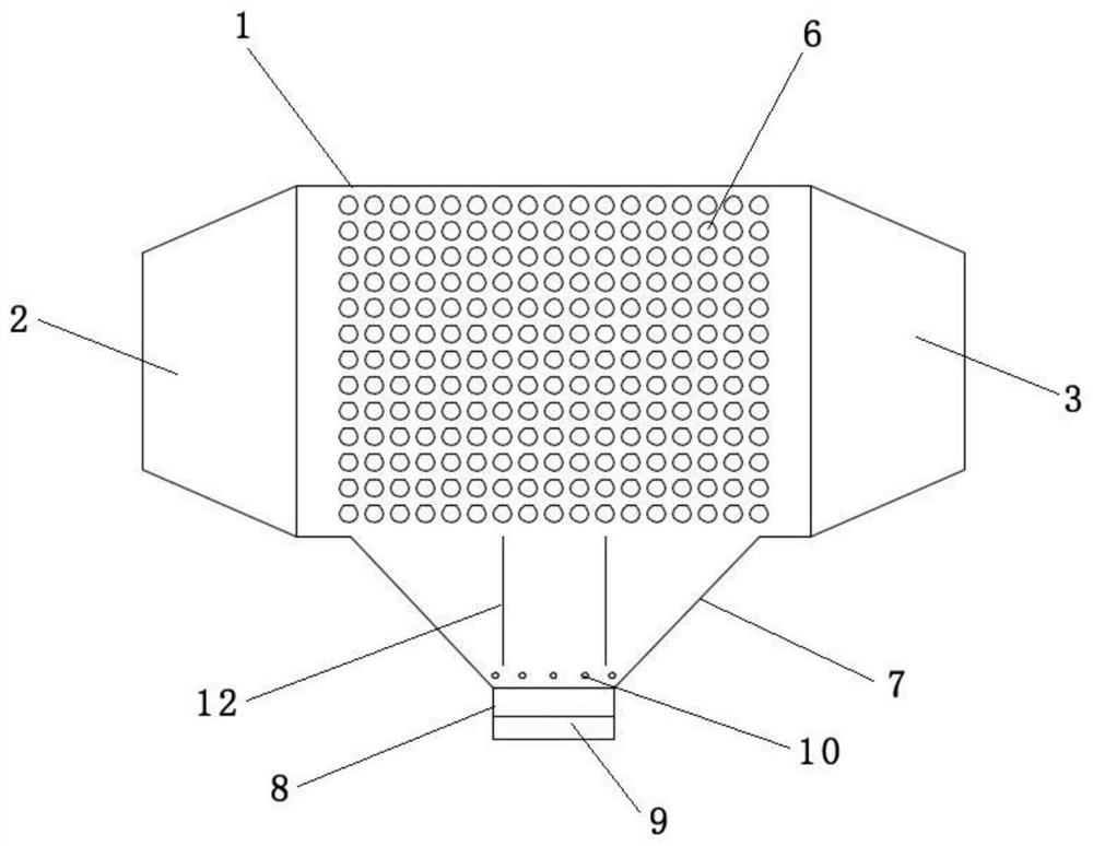
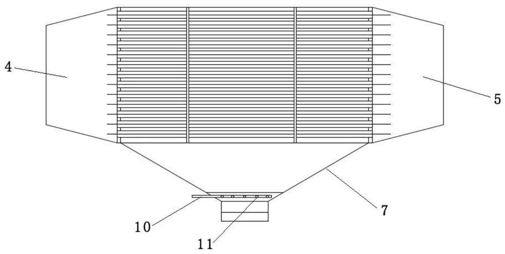
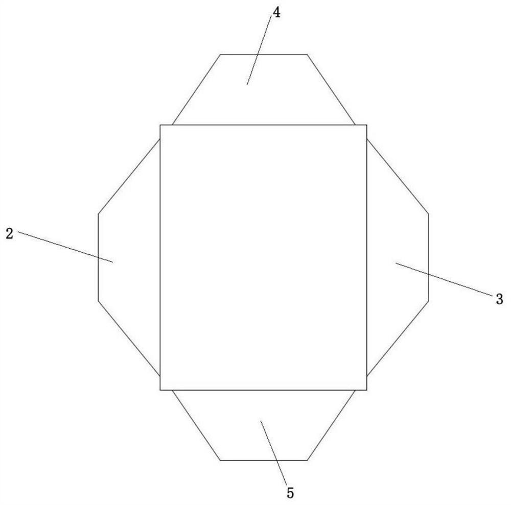
[0034] Such as Figure 1-3 As shown, a glass tube heat exchanger for preventing fouling from clogging includes a shell 1 . The shell 1 is respectively provided with flue gas inlet and outlet 2, 3 and air inlet and outlet 4, 5, and the shell 1 is provided with a heat exchange tube 6, the material of the heat exchange tube 6 is quartz glass, and the two ends of the heat exchange tube 6 Connect with air inlet and outlet 4 and 5 respectively. Both the heat exchange tube 6 and the flue gas flow channel are arranged horizontally. The lower part of the shell 1 is provided with an ash collection hopper 7, and the ash discharge port 8 at the lower end of the ash collection hopper 7 is provided with an ash discharge valve 9. There is a purge pipe 10, and one end of the purge pipe 10 protrudes from the ash collecting hopper 7 to connect with the air source. Scan hole 11.

[0035] The heat exchange tubes in the glass heat exchange tube assembly are arranged in a square, and the distanc...

Embodiment 2

[0040] Such as Figure 4 and 5As shown, a glass tube heat exchanger for preventing fouling from clogging includes a shell 1 . The shell 1 is respectively provided with flue gas inlet and outlet 2, 3 and air inlet and outlet 4, 5, and the shell 1 is provided with a heat exchange tube 6, the material of the heat exchange tube 6 is high borosilicate glass, and the heat exchange tube 6 The two ends communicate with the air inlet and outlet 4 and 5 respectively. The heat exchange tubes 6 are arranged horizontally, the flue gas flow channel is L-shaped, the flue gas inlet 2 is located on the side wall of the ash collecting hopper 7 , and the flue gas outlet 3 is located on the upper end surface of the shell 1 . The lower part of the housing 1 is provided with an ash collecting hopper 7, and the ash discharge port 8 at the lower end of the ash collecting hopper 7 is provided with an ash discharge valve 9, and the ash collecting hopper 7 is provided with a purge pipe 10, and one end...

Embodiment 3

[0042] Such as Figure 6 As shown, a glass tube heat exchanger for preventing fouling from clogging includes a shell 1 . The shell 1 is respectively provided with flue gas inlet and outlet 2, 3 and air inlet and outlet 4, 5, and the shell 1 is provided with a heat exchange tube 6, the material of the heat exchange tube 6 is quartz glass, and the two ends of the heat exchange tube 6 Connect with air inlet and outlet 4 and 5 respectively. The heat exchange tubes 6 are U-shaped or snake-shaped, the air inlets and outlets 4 and 5 are arranged on the upper surface of the shell 1, and the flue gas flow channels are arranged horizontally. The lower part of the housing 1 is provided with an ash collecting hopper 7, and the ash discharge port 8 at the lower end of the ash collecting hopper 7 is provided with an ash discharge valve 9, and the ash collecting hopper 7 is provided with a purge pipe 10, and one end of the purge pipe 10 protrudes from the collection The ash hopper 7 is con...


PUM


Abstract

The invention relates to a glass tube heat exchanger capable of preventing dust accumulation and blockage and application thereof. The glass tube heat exchanger comprises a shell, a smoke inlet and outlet and an air inlet and outlet are formed in the shell, a heat exchange tube is arranged in the shell, the two ends of the heat exchange tube communicates with the air inlet and outlet respectively, and an ash collecting hopper is arranged on the lower portion of the shell; and an ash discharging valve is arranged at an ash discharging opening in the lower end of the ash collecting hopper, a purging pipe is arranged in the ash collecting hopper, one end of the purging pipe extends out of the ash collecting hopper to be connected with an air source, and a plurality of purging holes are distributed in a pipe body, located in the ash collecting hopper, of the purging pipe. A dust collecting hopper is arranged at the bottom of the heat exchanger, dust mixed in smoke and crystallized salt separated out through cooling can be collected and discharged regularly in the heat exchange process, and the problem that the heat exchange efficiency is reduced due to the fact that the dust and the crystallized salt are attached to the pipe wall of the heat exchange pipe because the dust and the crystallized salt cannot be discharged is solved.

Description

technical field [0001] The invention relates to the technical field of heat exchange equipment, in particular to an anti-dust clogging glass tube heat exchanger and its application. Background technique [0002] In current industrial production, various heat exchangers are widely used for heat exchange, among which shell-and-tube heat exchangers are the most commonly used. Catalytic cracking is an important secondary processing in the oil refining process. It is an important means to increase the yield of light oil, produce high-octane gasoline, and produce more diesel oil at the same time. The catalytic cracking unit will emit a large amount of high-temperature flue gas during the catalytic cracking reaction process. The waste heat boiler is the main equipment for waste heat recovery of catalytic cracking units in petrochemical enterprises. The flue gas temperature at the outlet of the catalytic cracking waste heat boiler is 200-220 ° C. 260°C working condition. The flue ...

Claims


Application Information

Patent Timeline
Patent Type & Authority Applications(China)
IPC IPC(8): F28D7/16F28F21/00F23L15/00F23J15/06
CPCF28D7/1615F28F21/006F23L15/00F23J15/06Y02E20/34
Inventor 唐聚园邵松曲刚
Owner LUOYANG RUICHANG PETROCHEM EQUIP
Learn More