
Hydraulic turbine set vibration detection system and method

A vibration detection and water turbine technology, which is applied to vibration measurement in solids, vibration measurement, measurement devices, etc., can solve the problems of increased fitting clearance, unbalanced rotor, and misalignment of shafts, so as to reduce maintenance costs, reduce maintenance work, and reduce maintenance costs. The effect of prolonging the service life

Pending Publication Date: 2021-04-30
HEBEI UNIV OF ENG
View PDF5 Cites 1 Cited by
  • Summary
  • Abstract
  • Description
  • Claims
  • Application Information

AI Technical Summary

Problems solved by technology

[0003] In the daily use and maintenance of the water turbine unit, it is necessary to check various oil circuits, water circuits and electrical data. However, the machine wear, foundation sinking, component deformation, loose connection and dynamic performance of the machine equipment appear various subtleties. Most of the changes, such as shaft misalignment, component wear, rotor imbalance, and increased fit clearance, cannot be found directly through appearance changes. Therefore, it is necessary to carry out regular vibration detection on the unit to test the existence of equipment through changes in vibration parameters. Hidden dangers, and timely maintenance
[0004] However, periodic artificial vibration detection still cannot avoid some extreme situations, such as the lock of the generator shaft due to temperature rise caused by short-term vibration out of tolerance, etc., so a vibration detection system is urgently needed to measure the vibration value of the turbine Carry out real-time monitoring, and send an alarm in time when the vibration of the unit equipment is out of tolerance

Method used


Image

  • Hydraulic turbine set vibration detection system and method
  • Hydraulic turbine set vibration detection system and method
  • Hydraulic turbine set vibration detection system and method

Examples


Embodiment Construction

[0037] In order to make the technical problems, technical solutions and beneficial effects to be solved by the present invention clearer, the present invention will be further described in detail below in conjunction with embodiments. It should be understood that the specific embodiments described here are only used to explain the present invention, not to limit the present invention.

[0038] It should be noted that when an element is referred to as being “fixed” or “disposed on” another element, it may be directly on the other element or be indirectly on the other element. When an element is referred to as being "connected to" another element, it can be directly connected to the other element or indirectly connected to the other element.

[0039] In addition, the terms "first", "second", and "third" are used for descriptive purposes only, and cannot be interpreted as indicating or implying relative importance or implicitly specifying the quantity of the indicated technical f...


PUM


Abstract

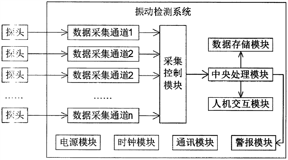
The invention discloses a hydraulic turbine set vibration detection system and method, on one hand, the hydraulic turbine set vibration detection system comprises a power supply module, a clock module, a communication module and a plurality of data acquisition channels, wherein the data acquisition channels are used for acquiring data obtained by corresponding probes; an acquisition control module used for controlling the data acquisition channels and sorting the acquired data; a central processing module used for processing the arranged data; a data storage module used for storing the data processed by the central processing module. The vibration monitoring system provided by the invention is used for carrying out real-time vibration detection on the hydraulic turbine set, and plays an important role in improving the utilization rate of hydraulic turbine set equipment, carrying out equipment maintenance in a planned manner, improving the water energy utilization rate and the like. After the detection system is used, the normal operation time of the hydraulic turbine set can be prolonged, the equipment operation condition is optimized, and the operation safety of the hydroelectric generating set is improved.

Description

technical field [0001] The invention relates to the technical field of hydraulic turbine unit detection, in particular to a hydraulic turbine unit vibration detection system and method. Background technique [0002] A water turbine is a power machine that converts the energy of water flow into rotational mechanical energy, and it belongs to the turbomachinery in fluid machinery. Most of the water turbines are installed in hydropower stations to drive generators to generate electricity. In a hydropower station, the water in the upstream reservoir is led to the turbine through the water diversion pipe, which drives the turbine runner to rotate, drives the generator to generate electricity, and the water after work is discharged downstream through the tail water pipeline. The higher the water head and the greater the flow, the greater the output power of the turbine. [0003] In the daily use and maintenance of the water turbine unit, it is necessary to check various oil circ...

Claims


Application Information

Patent Timeline
Patent Type & Authority Applications(China)
IPC IPC(8): G01H1/00
CPCG01H1/003
Inventor 曹庆皎王利英赵卫国王继选胡润志管一张少凯
Owner HEBEI UNIV OF ENG
Learn More