CT detection device based on capacitive coupling antenna and antenna manufacturing method

A technology of capacitive coupling and detection device, applied in the direction of antenna support/installation device, measurement device, antenna, etc., can solve the problem that the length and impedance of the antenna cannot meet the actual needs, reduce the transmission signal efficiency of the detection device, etc., to ensure the clarity , The effect of reducing signal attenuation and improving transmission efficiency

Active Publication Date: 2021-04-30
BEIJING HANGXING MACHINERY MFG CO LTD
View PDF8 Cites 1 Cited by
  • Summary
  • Abstract
  • Description
  • Claims
  • Application Information

AI Technical Summary

Problems solved by technology

[0004] However, due to the influence of technology and antenna material, the length and impedance of the existing capacitive coupling antenna cannot meet the actual needs, thus reducing the transmission signal efficiency of the detection equipment

Method used


Image

  • CT detection device based on capacitive coupling antenna and antenna manufacturing method
  • CT detection device based on capacitive coupling antenna and antenna manufacturing method

Examples


Embodiment Construction

[0052] Preferred embodiments of the present invention will be described in detail below in conjunction with the accompanying drawings, wherein the accompanying drawings constitute a part of the application and together with the embodiments of the present invention are used to explain the principle of the present invention and are not intended to limit the scope of the present invention.

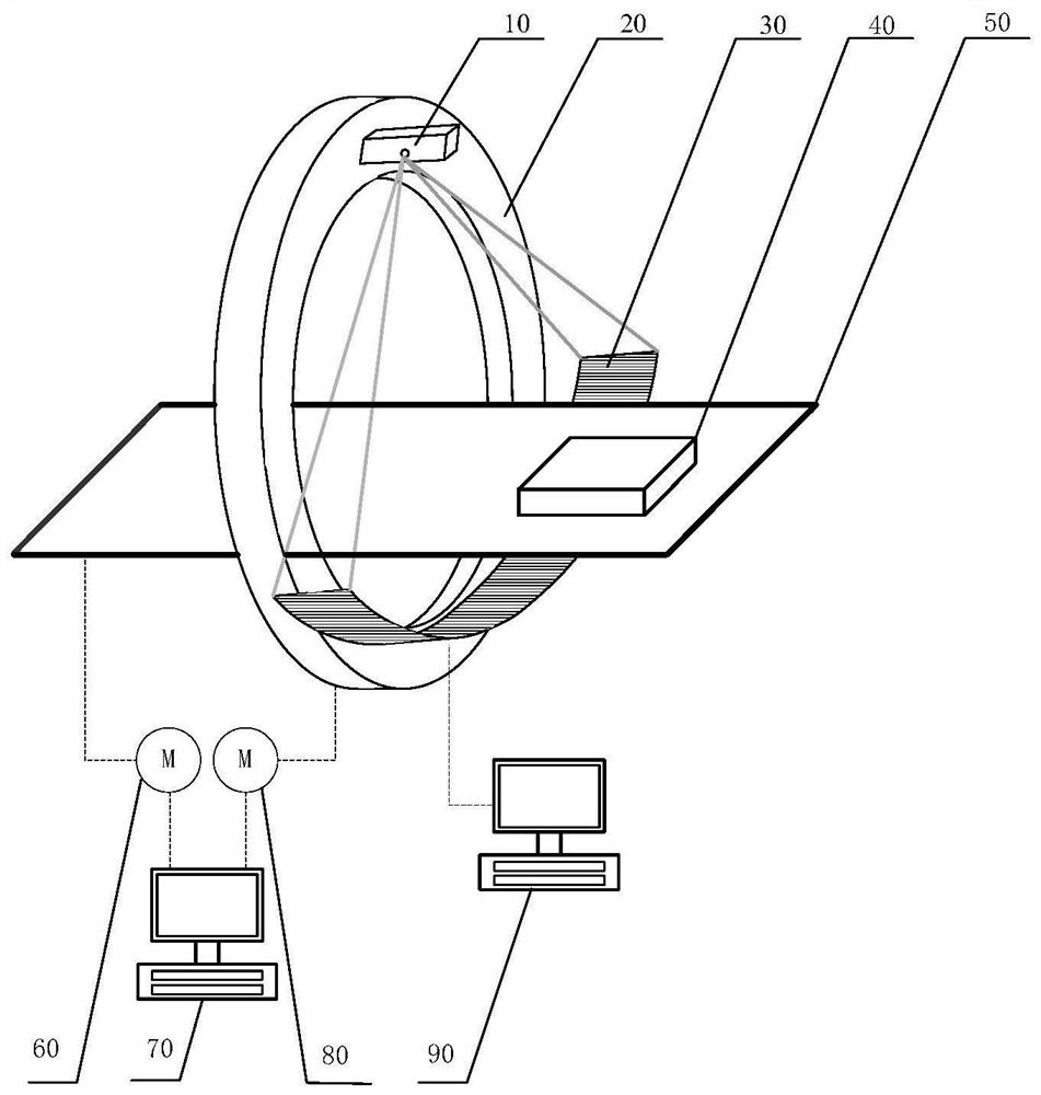
[0053] The structure of a CT device is usually as follows figure 1 As shown, it includes: a ray source 10 , a rotating disk 20 , a CT detector 30 , a conveyor belt 50 , a data processing unit 90 , a conveyor belt motor 60 , a slip ring motor 80 and a motion control computer 70 . The specific working method is that when the object 40 is inspected, the rotating disk 20 will rotate to drive the ray source 10 and the CT detector 30 to rotate 360 ​​degrees, so as to obtain images of the object 40 from multiple angles. Wherein, two capacitively coupled antennas are respectively wound along the circ...


PUM

PropertyMeasurementUnit
thicknessaaaaaaaaaa
widthaaaaaaaaaa
widthaaaaaaaaaa

Abstract

The invention relates to a CT detection device based on a capacitive coupling antenna and an antenna manufacturing method, which relate to the technical field of flexible circuits, and solve the problem that the length and impedance of an existing capacitive coupling type antenna cannot meet actual requirements. The CT detection device comprises a CT detector, a rotating disk, a capacitive coupling antenna and a data processing unit, wherein the CT detector is used for acquiring an image of a detected object, and transmitting the image of the detected object to the data processing unit through the capacitive coupling antenna; the CT detector and the capacitive coupling antenna are installed on the rotating disk; and the capacitive coupling antenna is an antenna made of a circuit board, and the material of the circuit board substrate comprises polyethylene and / or polytetrafluoroethylene. According to the technical scheme provided by the invention, the signal transmission efficiency of the detection equipment can be improved.

Description

technical field [0001] The invention relates to the technical field of flexible circuits, in particular to a capacitively coupled antenna-based CT detection device and an antenna manufacturing method. Background technique [0002] X-ray computed tomography imaging technology (abbreviated as "CT technology") is highly valued and widely used in the field of security inspection due to its own unique advantages. [0003] During the scanning process, the detection equipment needs to use the capacitive coupling antenna for real-time data interaction, and the capacitive coupling antenna is usually circular. [0004] However, due to the influence of technology and antenna material, the length and impedance of existing capacitively coupled antennas cannot meet actual needs, thereby reducing the transmission signal efficiency of detection equipment. Contents of the invention [0005] In view of the above analysis, the present invention aims to propose a capacitively coupled antenna...

Claims


Application Information

Patent Timeline
Patent Type & Authority Applications(China)
IPC IPC(8): G01N23/046H01Q1/22H01Q1/38G08C17/02
CPCG01N23/046H01Q1/225H01Q1/38G08C17/02
Inventor 刘晓超徐圆飞李保磊刘念翟利梁丽华李华宇
Owner BEIJING HANGXING MACHINERY MFG CO LTD
Why Eureka
Try Eureka