
Method for designing PCB coil device of wireless power transmission system

A wireless power transmission and coil device technology, applied in circuit devices, coils, coil manufacturing, etc., can solve the problems of large skin effect and proximity effect, affecting the overall parameters of the system, and easy deformation of coils, achieving skin effect and Low proximity effect, high transmission efficiency, and the effect of saving equipment volume

Active Publication Date: 2021-04-30
EAST CHINA NORMAL UNIV
View PDF6 Cites 3 Cited by
  • Summary
  • Abstract
  • Description
  • Claims
  • Application Information

AI Technical Summary

Problems solved by technology

The structure of the helical tightly wound coil is relatively simple, but this type of coil has a large volume because the wires are concentrated in one place, and because the coil is tightly wound, the heating and deformation of the wire are more difficult problems; the planar spiral The shape of the coil is similar to a disc-type mosquito coil. The radius of the coil gradually expands but they are all on the same plane to form a disc-shaped coil. Because its thickness is only one turn, this type of coil can be made relatively thin and is suitable for various types of equipment. Integration, greatly reducing the volume of the device, but the radius of each coil of this type of coil is inconsistent, so there is a certain directionality, and the transmission effect will also decrease when the coil deviates greatly; the space spiral structure coil is like For the springs seen in daily life, this type of coil has a large volume, and uses the natural resonant frequency of the coil to achieve resonance, so no external capacitor is needed, but this type of coil is prone to deformation, the humidity and temperature of the environment and the wire itself. Heat and expansion will have a great impact on the parameters of the coil
[0006] To sum up, the wireless power transmission device in the prior art has a large size, takes up equipment space, is difficult to match resonance, and has relatively large skin effect and proximity effect
Although there are practical use cases for PCB coils, they are currently designed with single-strand uniform wires. Because the current carried by the planar wires is small, there are also skin effects and proximity effects. Uneven heating of the wires causes deformation of the PCB coils, which in turn affects the system. overall parameters

Method used


Image

  • Method for designing PCB coil device of wireless power transmission system
  • Method for designing PCB coil device of wireless power transmission system
  • Method for designing PCB coil device of wireless power transmission system

Examples


Embodiment 1

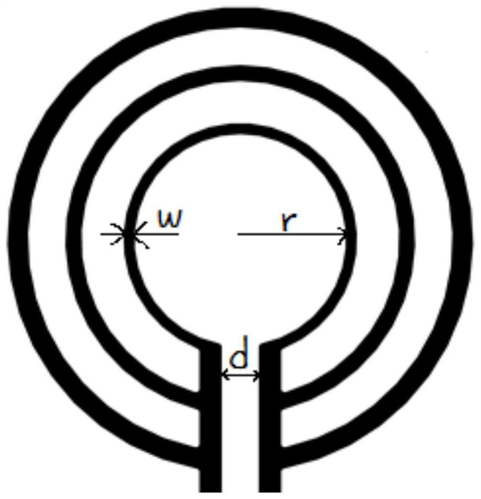
[0044] See attached figure 1 , the excitation-load coil device is composed of three parallel single-turn coils, and the radius of the coils should be larger in order to better excite the transmitting and receiving coils. Therefore, the innermost ring should not be designed too small, that is, the distance between two adjacent parallel coils should be as small as possible. The width w, radius r and resistance R of the coil are calculated by the following a formula:

[0045]

[0046] In the formula: h is the printing thickness. Considering the process reasons, the thickness of the PCB printed circuit should not be changed; ρ is the resistivity of the printing material. Generally, copper is used for PCB printing, and its resistivity is 1.75×10 -8 Ω·m; 2πr-d is the length of each coil; wh is the cross-sectional area of ​​the wire.

[0047] The inductance value of the coil can be regarded as the parallel connection of three individual coils, but the diameter and width of each ...

Embodiment 2

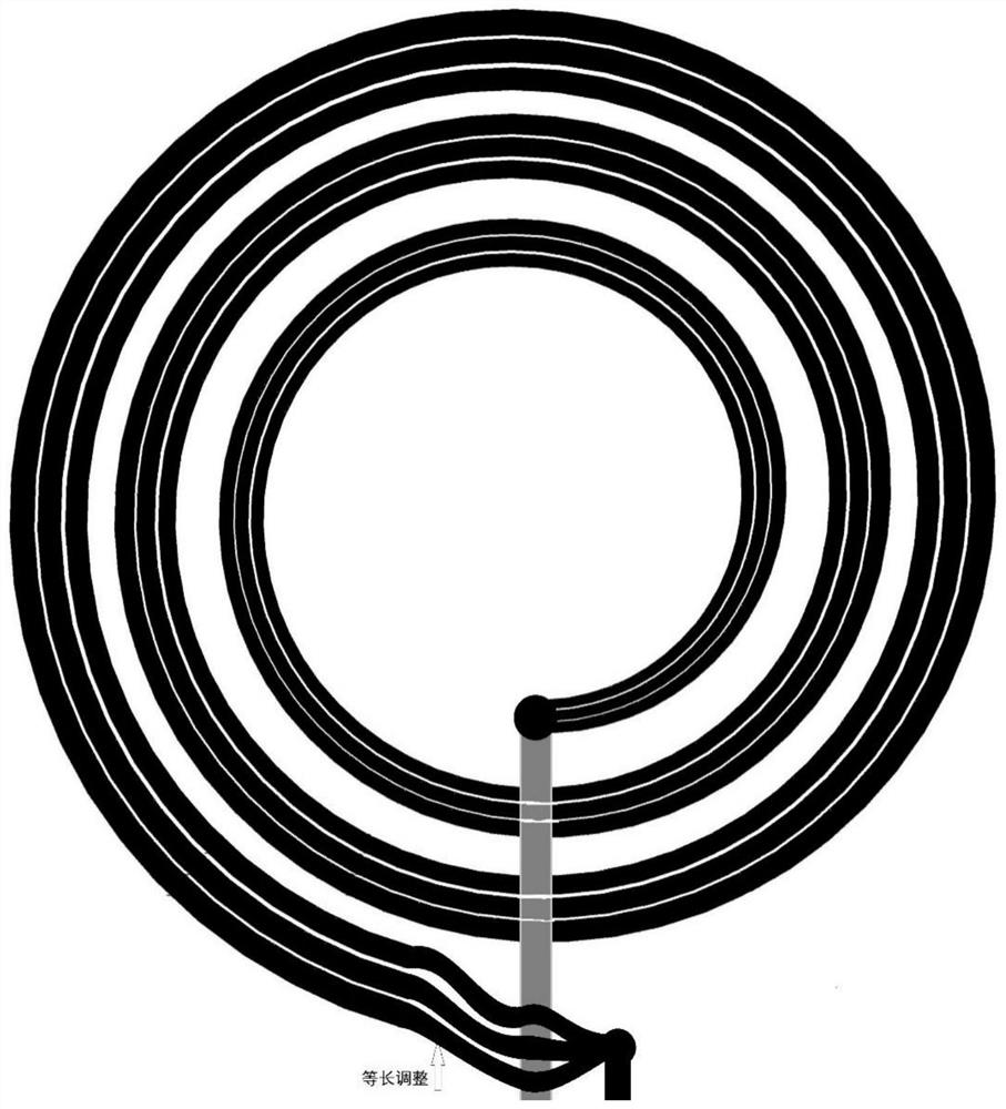
[0058] See attached figure 2 , the transmitting-receiving coil device is a planar helical coil composed of three thinner equal-length wires, and theoretically, the more turns of the thin wires, the better. The design of the coil with a thinner center and thicker edges can improve the performance of the coil. A serpentine bend is designed on the outer edge of the coil, which can change the length of the line without increasing the inductance, so that the resistance of each turn of the coil remains consistent. In actual design, in order to increase the conduction capacity of the coil, in addition to increasing the width of the coil, the coil can also be designed as a four-layer board or a multi-layer board. Multi-layer boards can also be used to increase the number of turns of the coil, so the inductance value of the coil device can be very precise.

[0059] The inductance value of the planar spiral coil can be obtained by finite element simulation like the excitation-load co...

Embodiment 3

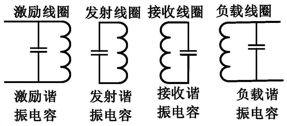
[0062] See attached Figure 3 ~ Figure 5 , taking the four-coil system as an example, according to the different connection methods of coils and capacitors in the circuit, it can be divided into three resonance forms: parallel-parallel, parallel-series and series-parallel.


PUM

PropertyMeasurementUnit
electrical resistivityaaaaaaaaaa

Abstract

The invention discloses a method for designing a PCB coil device of a wireless power transmission system; the method is characterized in that an excitation-load coil and a transmitting-receiving coil are designed on one or more layers of circuit boards by adopting a PCB to be printed into a PCB coil device of a two-coil system, a four-coil system or a relay coil system. Compared with the prior art, the coil device has the advantages of being small in equipment size, improving coil parameter precision and the like, the coil device can be attached to the surface of the equipment, the advantage of improving the miniaturization and attractiveness degree of the equipment is high, the transmission power and efficiency are high, and the skin effect and proximity effect of coils are greatly reduced. The method has high practical application value and commercial advantages in the field of future wireless power transmission.

Description

Technical field: [0001] The invention relates to the technical field of wireless power transmission, in particular to a method for designing a PCB coil device used in a wireless power transmission system. Background technique: [0002] Wireless power transmission technology can transmit energy to the load end without physical wire contact, and has a wide range of applications in future mobile electrical equipment, especially in mobile phones, robots, electric vehicles and other fields. The basic principle is to use the high-frequency changing magnetic field as the transmission medium, use two coils with the same resonance frequency, one as the transmitting end and the other as the receiving end, after the current of the resonant frequency is passed through the transmitting end, it will be in the surrounding A changing magnetic field of the same frequency is generated, and when the coil at the receiving end is within a certain magnetic field range, a resonant current of the s...

Claims


Application Information

Patent Timeline
Patent Type & Authority Applications(China)
IPC IPC(8): H01F5/00H01F41/04H02J50/12H02J50/50
CPCH01F5/003H01F41/041H02J50/12H02J50/502Y02T90/14Y02T10/70Y02T10/7072
Inventor 王友情郑正奇赵昆余超张海燕
Owner EAST CHINA NORMAL UNIV
Learn More