
Lithium ion battery system and fixing device thereof

A lithium-ion battery and fixing device technology, applied in the field of lithium-ion batteries, can solve problems such as increased battery loss, high temperature of battery modules, and low safety of lithium-ion battery systems

Inactive Publication Date: 2021-04-30
潘佳佳
View PDF8 Cites 0 Cited by
  • Summary
  • Abstract
  • Description
  • Claims
  • Application Information

AI Technical Summary

Problems solved by technology

[0004] In the actual application process, with the increase of operating time and power consumption of the battery module, when the current in the circuit is too large, the temperature of the battery module will be too high, and the loss of the battery will be increased if the temperature is not cooled in time. Even burned, the above problems lead to low safety of lithium-ion battery system

Method used


Image

  • Lithium ion battery system and fixing device thereof
  • Lithium ion battery system and fixing device thereof
  • Lithium ion battery system and fixing device thereof

Examples


Embodiment 1

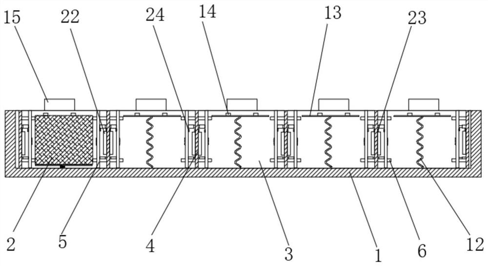
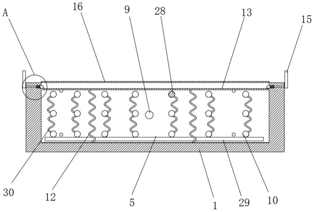
[0034] refer to Figure 1-8, a lithium-ion battery system, comprising a plurality of battery module cells 2 and a battery casing 1 with a plurality of cell installation cavities 3 inside, a heat-assisting assembly is arranged between two adjacent cell installation cavities 3, A plurality of battery module cells 2 and a plurality of heat aiding components are distributed between the heat aiding components at intervals. The heat aiding components include a fixed partition 4 and a pair of heat aiding modules 5, and a pair of heat aiding modules 5 are connected to the fixed spacer. On both sides of the plate 4, the side ends of the fixed partition 4 are clamped with the inner wall of the battery case 1, a pair of heat-assisting modules 5 can slide inside the battery case 1, and a memory expansion body is fixedly connected between the heat-assisted module 5 and the fixed partition 4 8. A plurality of heat dissipation holes 10 are provided on the heating aid module 5, and a dustproo...

Embodiment 2

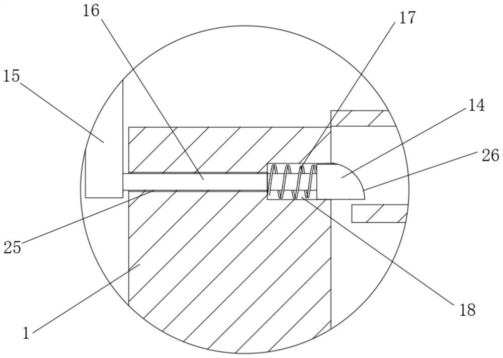
[0042] refer to Figure 1-4 and Figure 7 , a lithium-ion battery system. Compared with Embodiment 1, this embodiment also includes its fixing device for fixing the battery module unit 2. The fixing device includes a push plate 15, a push-pull rod 16, a limit block 14 and Compression spring 2 17, the battery housing 1 inner wall is provided with the receiving groove 18 that slides for limit block 14 and the through hole 25 that slides for push-pull rod 16, and through hole 25 is connected with receiving groove 18, and the two ends of push-pull rod 16 are respectively connected with The limit block 14 is fixedly connected with the push plate 15, the compression spring 17 is sleeved on the outside of the push-pull rod 16, and the two ends of the compression spring 17 are respectively fixedly connected with the inner wall of the storage groove 18 and the limit block 14, and the limit block 14 is away from the push-pull rod. The upper end of the tie rod 16 is set as an arc-shaped...


PUM


Abstract

The invention belongs to the technical field of lithium ion batteries, particularly relates to a lithium ion battery system and a fixing device thereof, and provides the following scheme directed at the technical problem that the safety of a lithium ion battery system is not high due to the fact that a battery module cannot be cooled in time when the temperature is too high: the lithium ion battery system comprises a plurality of battery module monomers and a battery shell, a plurality of monomer mounting cavities are formed in the inner side of the battery shell, a heat assisting assembly is arranged between every two adjacent monomer mounting cavities, each heat assisting assembly comprises a fixed partition plate and a pair of heat assisting modules, a memory telescopic body is fixedly connected between each heat assisting module and the corresponding fixed partition plate, and a plurality of heat dissipation holes are formed in each heat assisting module. According to the invention, when the temperature of the battery module monomers is too high, and accordingly the temperature of the heat assisting modules is also too high, the memory telescopic bodies contract to drive the heat assisting modules to be far away from the battery module monomers, so that the heat assisting modules are prevented from continuously heating the battery module monomers, and the heat dissipation holes formed in the heat assisting modules can be used for stably dissipating heat of the battery module monomers, and the high-temperature loss of the battery module monomers is reduced.

Description

technical field [0001] The invention relates to the technical field of lithium-ion batteries, in particular to a lithium-ion battery system and a fixing device thereof. Background technique [0002] Low temperature is an obstacle to the promotion of electric vehicles in northern my country and alpine regions, and it is also a heart problem for power battery companies. Overcoming the low temperature resistance of power batteries has always been one of the key efforts of the industry. At present, the feasible and effective method for enterprises to solve low-temperature batteries is to preheat the batteries, that is, to use PTC, resistors, heat pipes and phase change materials to preheat systems. However, this method needs to rely on external energy to heat the materials, which is subject to a large Moreover, these preheating methods have low heating efficiency and high energy consumption. Not only that, but in some harsh environments, including acid-base, humid, high temperat...

Claims


Application Information

Patent Timeline
IPC IPC(8): H01M50/204H01M50/24H01M10/613H01M10/615H01M10/625H01M10/655H01M10/6563H01M10/657
CPCH01M10/613H01M10/615H01M10/625H01M10/655H01M10/6563H01M10/657Y02E60/10
Inventor 潘佳佳
Owner 潘佳佳
Features
  • Generate Ideas
  • Intellectual Property
  • Life Sciences
  • Materials
  • Tech Scout
  • Unparalleled Data Quality
  • Higher Quality Content
  • 60% Fewer Hallucinations
Learn More