Ultra-low-frequency nuclear electromagnetic pulse receiving antenna

A nuclear electromagnetic pulse and receiving antenna technology, applied in the direction of antenna, antenna grounding switch structure connection, electrical components, etc., can solve the problems of easy interference of output signals, easy mutual interference waveform, poor antenna directivity, etc., to achieve small antenna size, Good directivity and little signal distortion

Pending Publication Date: 2021-04-30
中国电波传播研究所
View PDF3 Cites 3 Cited by
  • Summary
  • Abstract
  • Description
  • Claims
  • Application Information

AI Technical Summary

Problems solved by technology

[0003] However, at present, there are few studies on the design of very low frequency nuclear electromagnetic pulse receiving antennas, and the general design method of lightning electromagnetic pulse receiving antennas is still mainly used, which has the following problems: 1) The electric field receiving antenna and the magnetic field receiving antenna are arranged separately, and the structure is complicated It is bulky; 2) The electric field receiving antenna adopts a whip antenna, which is inconvenient to use; 3) The magnetic field receiving antenna adopts an open loop antenna, which has poor directivity and is easy to interfere with each other to cause waveform distortion; Small, the output signal is susceptible to interference, and there is no special anti-noise filter processing for the very low frequency nuclear electromagnetic pulse receiving function

Method used


Image

  • Ultra-low-frequency nuclear electromagnetic pulse receiving antenna
  • Ultra-low-frequency nuclear electromagnetic pulse receiving antenna
  • Ultra-low-frequency nuclear electromagnetic pulse receiving antenna

Examples


Embodiment 1

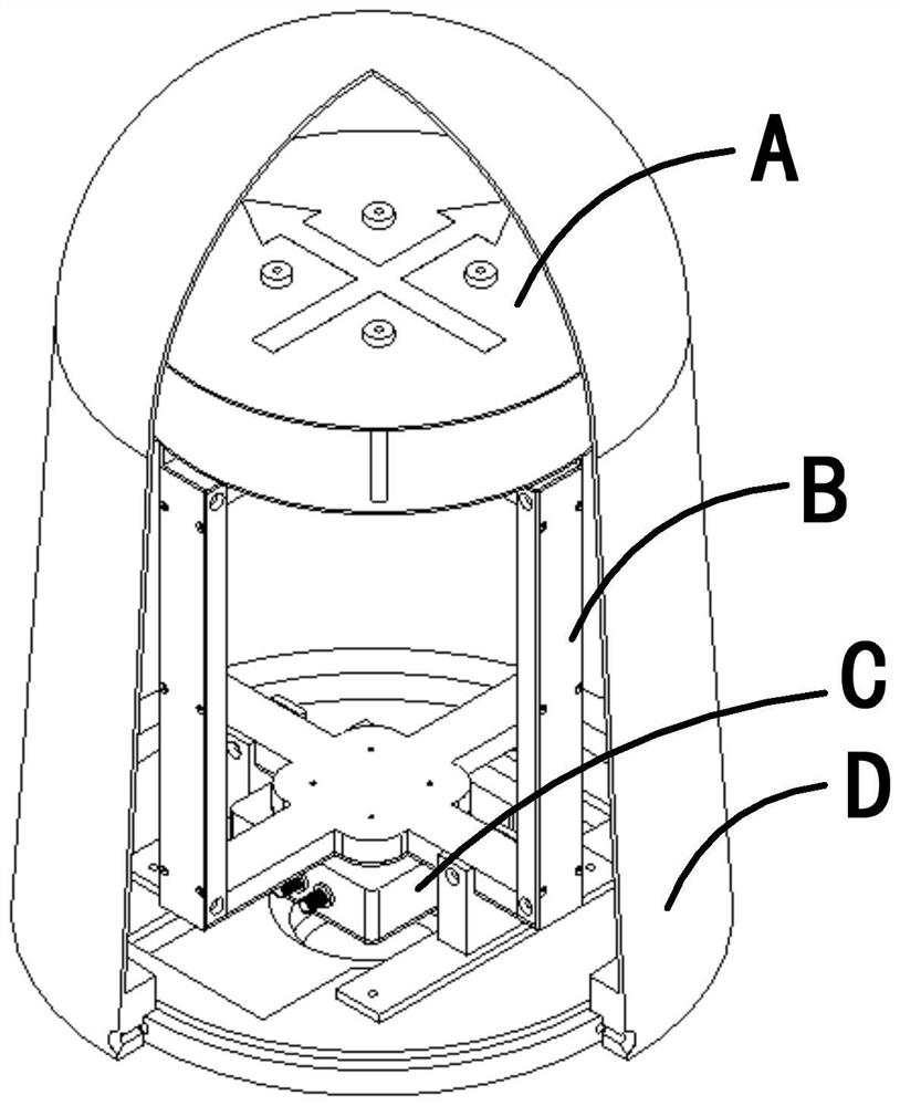
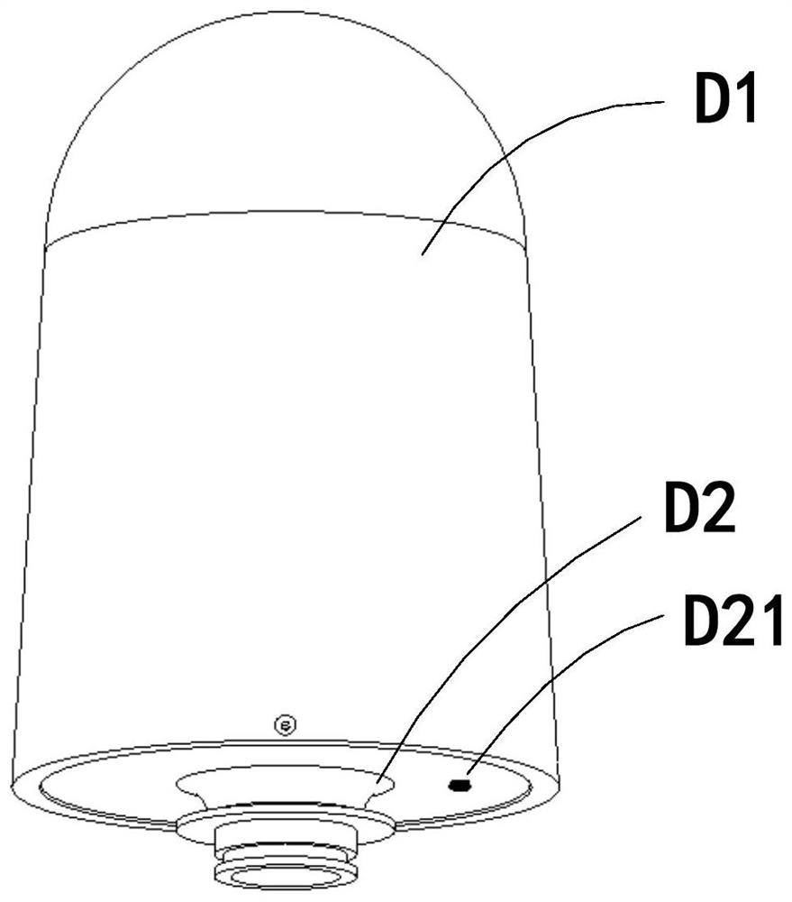
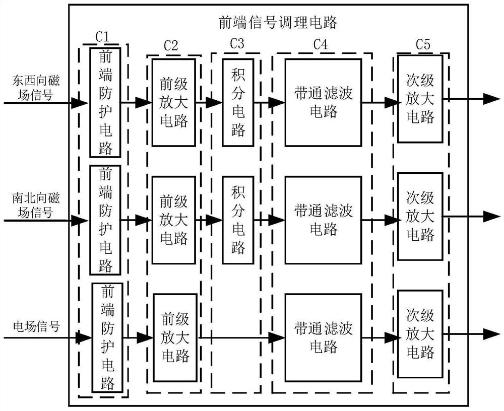
[0030] Example 1, such as figure 1 As shown, this embodiment discloses a very low frequency nuclear electromagnetic pulse receiving antenna, including a radome D composed of a shell and a base, a signal output interface and a power supply input interface are arranged on the base, and a circuit board installation box is arranged on the top of the base A signal conditioning circuit C is installed in the circuit board installation box, a signal output terminal electrically connected to the above-mentioned signal output interface and a power supply input terminal electrically connected to the above-mentioned power supply input interface are arranged on the signal conditioning circuit, on the top of the circuit board installation box The magnetic field receiving antenna B is installed, the electric field receiving antenna A is installed on the top of the magnetic field receiving antenna, and the magnetic field receiving antenna and the electric field receiving antenna are respective...


PUM


Abstract

The invention discloses an ultra-low-frequency nuclear electromagnetic pulse receiving antenna which comprises an antenna cover composed of a shell and a base, a signal output interface and a power supply input interface are arranged on the base, a circuit board installation box is arranged at the top of the base, and a signal conditioning circuit is installed in the circuit board installation box. A signal output end electrically connected with the signal output interface and a power supply input end electrically connected with the power supply input interface are arranged on the signal conditioning circuit, a magnetic field receiving antenna is installed at the top of the circuit board installation box, and an electric field receiving antenna is installed at the top of the magnetic field receiving antenna. According to the ultra-low-frequency nuclear electromagnetic pulse receiving antenna disclosed by the invention, various defects in the prior art are overcome, acquisition and receiving of ultra-low-frequency nuclear electromagnetic pulse waveform signals can be better realized, the sensitivity, the dynamic range and the anti-interference performance of the antenna are improved, and meanwhile, the miniaturization and the usability of the antenna are ensured.

Description

technical field [0001] The invention belongs to the technical field of antennas, in particular to a very low frequency nuclear electromagnetic pulse receiving antenna in the field. Background technique [0002] The nuclear electromagnetic pulse is a secondary effect that must accompany the nuclear explosion, mainly due to the excitation of the gamma rays released during the nuclear explosion. The very low frequency component of the electromagnetic pulse generated by the nuclear explosion can propagate far away through the earth wave guide formed between the earth and the ionosphere, with small propagation attenuation and stable phase, and the propagation distance can reach more than thousands of kilometers. By receiving and analyzing very low frequency nuclear electromagnetic pulse waveforms, nuclear explosion events can be monitored, parameters such as nuclear explosion equivalent can be analyzed, and nuclear explosion sites can also be located through multi-station joint r...

Claims


Application Information

Patent Timeline
Patent Type & Authority Applications(China)
IPC IPC(8): H01Q23/00H01Q1/42H01Q1/50
CPCH01Q23/00H01Q1/42H01Q1/50
Inventor 刘杨陈奇东刘睿黄晓徐文璞甄卫民熊雯吴松泽王森苗晋葳
Owner 中国电波传播研究所
Why Eureka
Try Eureka