A self-adaptive soft drive control circuit

A control circuit and soft drive technology, which is applied in the direction of control/regulation system, electrical components, and adjustment of electrical variables, can solve the problems of large current peaks and poor EMI characteristics, and achieve the effect of simple control loop structure and improved EMI characteristics

Active Publication Date: 2022-06-24
NANJING MICRO ONE ELECTRONICS
View PDF0 Cites 0 Cited by
  • Summary
  • Abstract
  • Description
  • Claims
  • Application Information

AI Technical Summary

Problems solved by technology

[0006] The purpose of the present invention is to provide an adaptive soft drive control circuit, which has the advantage of realizing the self-adaptive adjustment of the flyback primary side MOS drive, and solves the instantaneous current peak of the switch caused by the excessive driving speed of the primary side in the ACDC system. Large, poor EMI characteristics

Method used


Image

  • A self-adaptive soft drive control circuit
  • A self-adaptive soft drive control circuit
  • A self-adaptive soft drive control circuit

Examples


Embodiment Construction

[0029] The technical solutions in the embodiments of the present invention will be clearly and completely described below with reference to the accompanying drawings in the embodiments of the present invention. Obviously, the described embodiments are only a part of the embodiments of the present invention, but not all of the embodiments. Based on the embodiments of the present invention, all other embodiments obtained by those of ordinary skill in the art without creative efforts shall fall within the protection scope of the present invention.

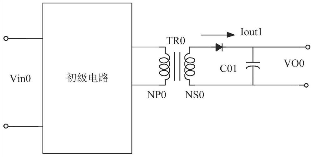
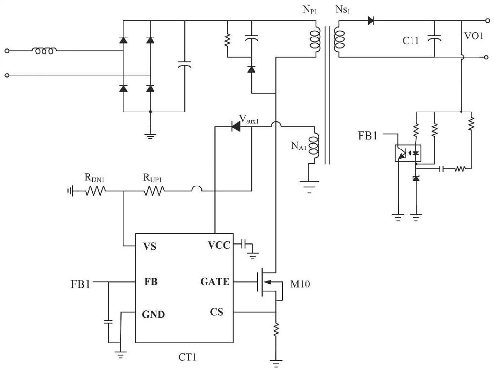
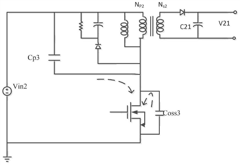
[0030] refer to Figure 1-7 , an adaptive soft drive control circuit, including a basic circuit, the basic circuit includes an external power MOS, and also includes a driving speed detection circuit and a dynamic adjustment circuit;

[0031] The driving speed detection circuit is used to receive the source voltage of the power MOS, determine whether to adjust the driving speed, and output an enable signal;

[0032] The dynamic adjust...


PUM


Abstract

The invention discloses an adaptive soft drive control circuit, which includes a basic circuit, the basic circuit includes an external power MOS, and a driving speed detection circuit and a dynamic adjustment circuit, and the driving speed detection circuit is used to receive the The source voltage of the power MOS determines whether to adjust the driving speed, and outputs an enabling signal. The dynamic adjustment circuit is used to receive the enabling signal and gradually change the driving current of the power MOS until the driving speed is maintained at a preset value. near the set value. The present invention directly samples the current peak at the moment when the external power switch is turned on by detecting the voltage peak of the external CS pin of the chip. The port is externally connected to the ground resistor to realize the adjustable end point of self-adaptive adjustment.

Description

technical field [0001] The present invention relates to the technical field of power supply, in particular to an adaptive soft drive control circuit. Background technique [0002] Flyback circuit such as figure 1 , the primary side NP0 of TR0 of the transformer is connected to the primary circuit, the input voltage Vin0 is input into the primary circuit, the primary uses the input voltage to realize the energy storage of the excitation inductance, and transmits it to the secondary, the diode D01 of the secondary measuring NS0 flows through the output current Iout1, Iout1 charges the capacitor C01 and provides energy to the load. [0003] In order to achieve the optimal efficiency of the switching power supply, the quasi-resonant control mode is usually used, and the whole system works in the discontinuous mode (DCM) at this time. figure 2 The flyback topology working under DCM is given. When the voltage VO1 on the secondary output capacitor C11 is lower than the rated out...

Claims


Application Information

Patent Timeline
Patent Type & Authority Patents(China)
IPC IPC(8): H02M3/335H02M1/44H02M1/32
CPCH02M3/33592H02M1/44H02M1/32
Inventor 鲁扬张洪俞黎敏霞
Owner NANJING MICRO ONE ELECTRONICS
Why Eureka
Try Eureka