Motor abnormality protection circuit

An abnormality protection and circuit technology, applied in the direction of motor control, electrical components, control systems, etc., can solve problems such as bus voltage rise, motor burnout, component aging failure, etc., to reduce reverse speed, protect mechanical structure, and small size Effect

Active Publication Date: 2021-06-29
CHINA AUTOMOTIVE INNOVATION CORP
View PDF6 Cites 0 Cited by
  • Summary
  • Abstract
  • Description
  • Claims
  • Application Information

AI Technical Summary

Problems solved by technology

However, if abnormal working conditions such as power failure of the braking system occur, the software control function of the control system of the braking system will also fail due to power failure, and the high-pressure brake fluid will push the motor to reverse rapidly. So it becomes a generator, high-speed reverse power generation, the current will charge the capacitor in the motor bus power network through the body diode of the upper arm of the drive bridge, because of the single-phase conductivity of the body diode, the bus voltage will continue to rise after charging, over High voltage can damage electronic components and even burn the motor
[0004] The traditional solution is as figure 2 As shown, components such as high-power electronic voltage regulator tubes are used as passive energy absorbing devices to suppress the high voltage generated by motor reversal. When the bus voltage is too high, the voltage regulator components break down and conduct and discharge energy. However, this scheme has the following A few questions: A. High-power passive components are large in size and high in price, which has a great negative impact on system volume and cost
[0006] C. High-power passive components are affected by current impact loss, their own life, and differences in process consistency. There is a risk of random failure and fatigue failure, resulting in a decrease in protection effect or even a complete loss, especially when the battery is not firmly connected and the contact is poor. When, multiple strong current discharges will accelerate the aging and failure of components

Method used


Image

  • Motor abnormality protection circuit
  • Motor abnormality protection circuit
  • Motor abnormality protection circuit

Examples


Embodiment Construction

[0053] In the following description, numerous specific details are given in order to provide a more thorough understanding of the present invention. It will be apparent, however, to one skilled in the art that the present invention may be practiced without one or more of these details. In other examples, some technical features known in the art are not described in order to avoid confusion with the present invention.

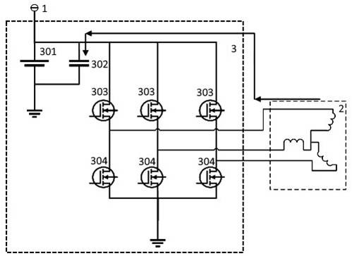
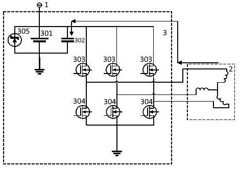
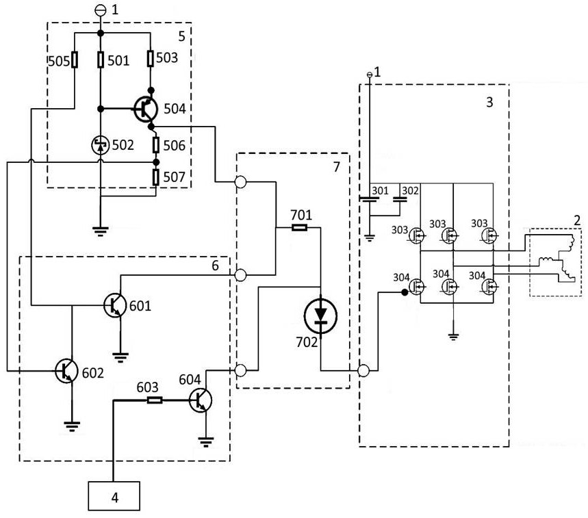
[0054] Existing technologies such as figure 1 and 2 When the drive circuit of the motor shown is damaged or the system is abnormally powered off, the generated current generated by the uncontrolled reverse rotation of the motor goes to the upper arm of the drive bridge to charge the bus capacitor, and there is a problem that the bus voltage is too high. In order to solve the above problems, the applicant developed A motor abnormality protection circuit and protection method are provided.

[0055] The motor abnormal protection circuit includes: drive bridge m...


PUM


Abstract

The invention discloses a motor abnormal protection circuit, which belongs to the field of emergency protection circuits. The circuit includes: a drive bridge module, a drive output module, a function control module and a voltage monitoring module, the drive bridge module includes a discharge control unit configured to receive the discharge voltage and ground the motor winding, the drive output module is connected to the drive bridge module, It is set to input the discharge voltage to the drive bridge module, the function control module is connected to the drive output module, and is set to limit the drive output module to input the discharge voltage to the drive bridge module, and the voltage monitoring module is used to monitor the voltage of the bus, respectively connected to the drive output module The output module is connected with the function control module. By adding a voltage monitoring module, the present invention can use circuit hardware to detect the bus voltage when the control system fails, and actively guides and discharges the generated current to the ground by driving the output module to prevent abnormal rise of the bus voltage.

Description

technical field [0001] The invention belongs to the field of emergency protection circuits, in particular to a motor abnormality protection circuit. Background technique [0002] With the maturity of electronic power assist system technology, taking into account factors such as cost, space, weight, and performance, not only electric vehicles, but also more and more fuel vehicles use braking systems integrated with electronic power assist functions. The core of the electronic booster part in the braking system is a three-phase brushless motor. By controlling the rotation of the brushless motor and cooperating with the opening and closing of the solenoid valve, the brake fluid is delivered from the master cylinder to the wheel cylinder to provide the required power to the wheel cylinder. brake pressure. [0003] During the braking process, the motor pushes the piston to compress the brake fluid, and the pressure of the brake fluid increases continuously, which exerts a revers...

Claims


Application Information

Patent Timeline
Patent Type & Authority Patents(China)
IPC IPC(8): H02P29/024
CPCH02P29/0241
Inventor 李丰军周剑光
Owner CHINA AUTOMOTIVE INNOVATION CORP
Why Eureka
Try Eureka