
Flow-disturbing type air inlet pipe of muffler

A technology of intake pipe and muffler, which is applied in the direction of muffler, machine/engine, engine components, etc. It can solve the problems of insufficient combustion of mixture gas, power loss, increase of pollutant emissions, etc., and achieves simple structure and is conducive to production and installation , Beautiful effect

Inactive Publication Date: 2007-10-24
LONGXIN IND GROUP
View PDF1 Cites 0 Cited by
  • Summary
  • Abstract
  • Description
  • Claims
  • Application Information

AI Technical Summary

Problems solved by technology

As a result, there is insufficient fresh air mixture entering the cylinder, resulting in insufficient combustion of the air mixture, resulting in fuel loss, increased emission of pollutants, and power loss
The above-mentioned patent does not solve the technical problem of "back pressure" in the internal combustion engine

Method used


Image

  • Flow-disturbing type air inlet pipe of muffler
  • Flow-disturbing type air inlet pipe of muffler
  • Flow-disturbing type air inlet pipe of muffler

Examples


Embodiment Construction

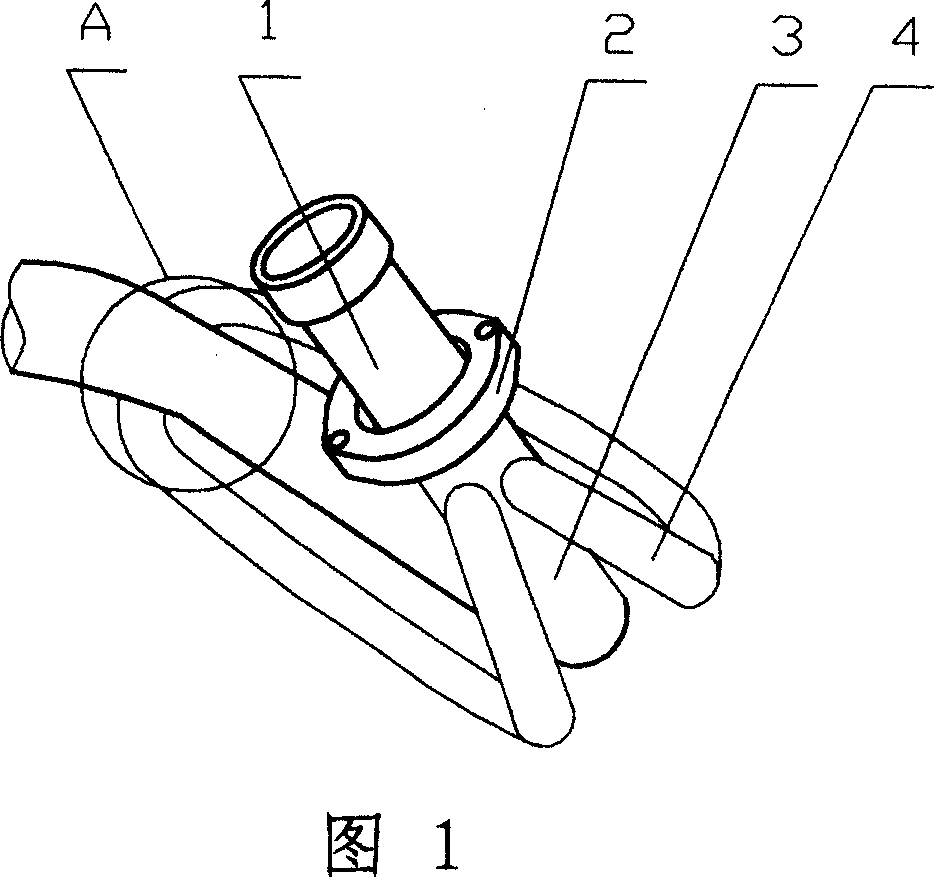
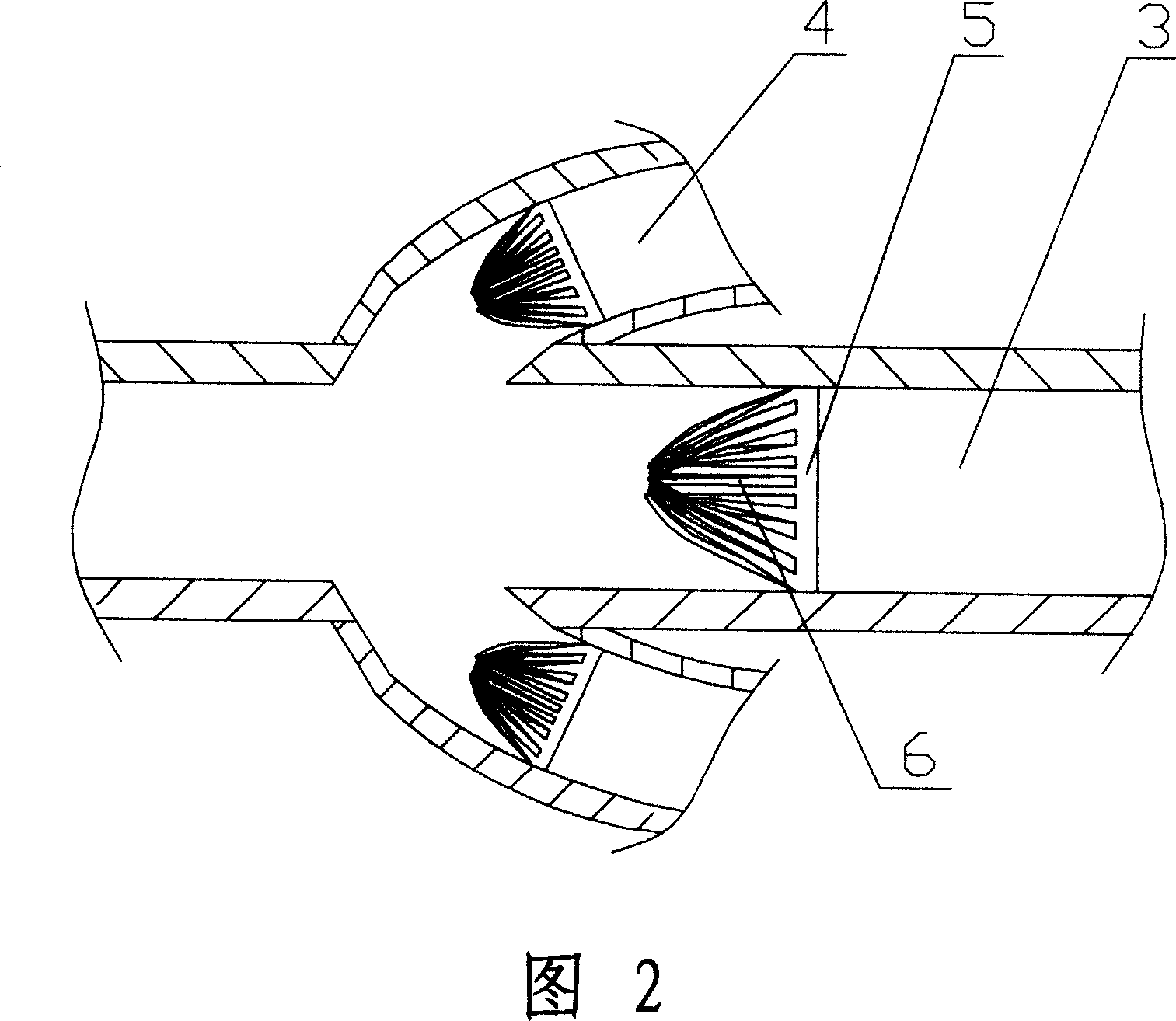
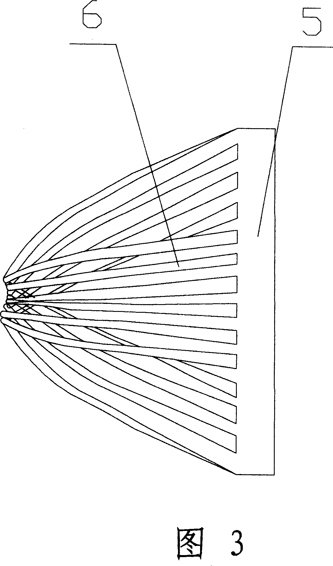
[0010] Referring to Figure 1, Figure 2, and Figure 3, a flange 2 is provided at the inlet end of the inlet pipe 1 of the muffler. The air inlet pipe 1 is formed by welding two curved ducts 4 for turbulence on a curved main airflow duct 3, and the two ducts 4 for turbulence are juxtaposed on both sides of the main airflow duct 3. The head and tail ends of 4 are welded to the wall of the main air duct 3 and communicate with the main air duct 3. The head ends of the two turbulent ducts 4 for flow splitting are welded to the circumference of the same section of the main airflow duct 3 close to the flange plate 2. The end and the main airflow duct 3 form an angle of less than 45 degrees; the tail ends of the two turbulent ducts 4 for turbulence are welded to the main airflow duct 3 on the same section of the circumference close to the muffler tube, two The tail end outlets of the turbulence duct 4 for turbulence are arranged symmetrically opposite to each other centered on the main air...


PUM


Abstract

The present invention discloses a flow-disturbing air inlet pipe of dissipative muffler. The air inlet end connecting head of air inlet pipe is equipped with flange, said air inlet pipe is composed by welding at least two conduits used for disturbing flow on the main flow conduit, the conduits used for disturbing flow are installed two sides of main flow conduit, the head and tail ends used for disturbing flow is welded on the conduit wall of main flow conduit and connected with main flow conduit. The invention not only can change the sonic wave frequency to reduce noise through reducing the energy and initial speed of air flow, but also can reduce the back pressure of combustion engine effectively and increase the power of combustion engine. Its structure is simple and it is benefit for production and installation, and the conduit used for disturbing flow of air inlet pipe can make the shape of motor bicycle is more attractive when it is installed on motor bicycle.

Description

Technical field [0001] The invention relates to a muffler, in particular to a turbulent air intake pipe of a muffler of an internal combustion engine. Background technique [0002] At present, the muffler of the internal combustion engine mainly adopts the principle of sound absorption, resonance, interference, expansion, frequency conversion, and equalization. Through resistance or resistance, the high-pressure exhaust gas discharged from the internal combustion engine is consumed to achieve the purpose of reducing noise. However, the use of the above-mentioned principle to achieve noise reduction cannot effectively improve the power of the internal combustion engine, and the unity between the two in terms of noise reduction and improvement of the internal combustion engine power cannot be achieved. In view of the contradiction between noise reduction and improvement of internal combustion engine power, a muffler disclosed in Chinese patent CN200420033112.9 has made a certain te...

Claims


Application Information

Patent Timeline
Patent Type & Authority Applications(China)
IPC IPC(8): F01N1/00
Inventor 庹建品何浪刘成果张优红牛树松
Owner LONGXIN IND GROUP
Learn More