Underwater wireless optical communication receiving method and device based on gain control in detector

A wireless optical communication and receiving device technology, applied in electromagnetic wave transmission systems, electrical components, transmission systems, etc., can solve the variable attenuator increase receiver size, weight and complexity, increase the transmitter and receiver alignment requirements , reduce the field of view of the receiver, etc., to achieve the effect of increasing the range of received optical power, simple structure, and easy promotion and application

Active Publication Date: 2021-04-30
XIDIAN UNIV
View PDF3 Cites 1 Cited by
  • Summary
  • Abstract
  • Description
  • Claims
  • Application Information

AI Technical Summary

Problems solved by technology

However, the existence of the variable attenuator will increase the volume, weight and complexity of the receiver, which will bring inconvenience to the use of the equipment
In addition, the existence of the variable attenuator will reduce the field of view of the receiver to a certain extent, which will increase the alignment requirements of the transmitter and receiver during communication

Method used


Image

  • Underwater wireless optical communication receiving method and device based on gain control in detector
  • Underwater wireless optical communication receiving method and device based on gain control in detector
  • Underwater wireless optical communication receiving method and device based on gain control in detector

Examples


Embodiment 1

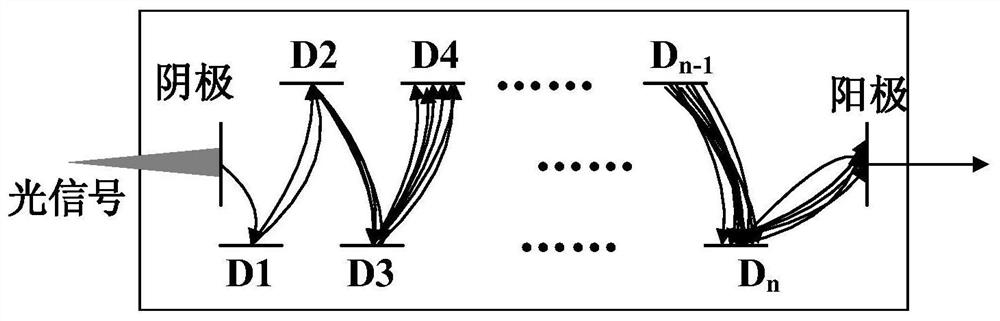
[0037] First, the working principle of the photomultiplier tube device is explained. The photomultiplier tube device (Photomultiplier Tube, PMT) can convert optical signals into electrical signals. It is a high-sensitivity photodetector device and is often used in underwater wireless optical communication receivers. , convert the optical signal received by the receiver into an electrical signal. See figure 1 , figure 1 It is a schematic diagram of the working principle of the photomultiplier tube of the embodiment of the present invention. As shown in the figure, the photomultiplier tube is mainly composed of a photoemission cathode (photocathode), an electron multiplication dynode and an electron collector (anode). When light hits the photocathode, the photocathode excites photoelectrons into the vacuum. These photoelectrons enter the multiplication system under the action of an external electric field, and the photoelectrons are multiplied and amplified by the secondary e...


PUM


Abstract

The invention relates to an underwater wireless optical communication receiving method and device based on gain control in a detector. The method comprises the following steps: S1, converting a received communication optical signal into a communication current signal by using a photomultiplier; S2, converting the communication current signal into a communication voltage signal; S3, generating a DC voltage according to the communication voltage signal, and controlling the internal gain change of the photomultiplier by using the DC voltage so as to control the amplitude change of the communication voltage signal, thereby enlarging the receiving optical power range of the receiving device, wherein the communication voltage signal is used as an electric signal subsequently processed by the receiving device. According to the method, detection of different optical power signals is achieved through the method of controlling the internal gain of the photomultiplier through the direct-current voltage, the receiving optical power range of the receiving device is enlarged, and rapid response can be achieved for the signals with different optical powers.

Description

technical field [0001] The invention belongs to the technical field of underwater wireless communication, and in particular relates to an underwater wireless optical communication receiving method and device based on detector internal gain control. Background technique [0002] Wireless communication technology is very important in the field of underwater communication. Whether it is the return of seabed monitoring data or the information interaction between underwater mobile platforms, efficient data transmission is required. Among them, underwater wireless optical communication using blue-green light waves as information carriers has broad application prospects in the field of short-distance underwater wireless transmission due to its outstanding advantages such as high transmission rate, low delay, light weight, and small power consumption. Become an important development direction of marine communication. [0003] In practical applications, the power of the communicatio...

Claims


Application Information

Patent Timeline
Patent Type & Authority Applications(China)
IPC IPC(8): H04B10/293H04B13/02
CPCH04B10/2931H04B13/02
Inventor 韩彪鲁振中吕沛孙艳玲马琳廖家莉李璞张博肖国尧
Owner XIDIAN UNIV
Why Eureka
Try Eureka