Asphalt steam thermal cycle foaming system

A foaming system and heat cycle technology, applied in the field of asphalt production and processing, can solve the problems of waste of resources, imbalance of asphalt and water ratio, difficulty in controlling the amount of water injection, etc., and achieve the effect of improving utilization rate and quality of finished products

Active Publication Date: 2021-05-04
YICHANG JIANGXIA MARINE MACHINERY
View PDF8 Cites 0 Cited by
  • Summary
  • Abstract
  • Description
  • Claims
  • Application Information

AI Technical Summary

Problems solved by technology

[0003] In the existing asphalt foaming process, the heated asphalt is usually placed in the mixing chamber to mix and foam with air and water droplets. The water outlet of the existing foaming device is usually fixed, and the water droplets are continuously sprayed through the same part. This process easily leads to uneven asphalt foaming; it is difficult to control the amount of water injected into the asphalt in the form of water droplets during the foaming process, resulting in an imbalance in the ratio of asphalt and water, which affects the quality of asphalt foaming; the process of asphalt mixing also Need to maintain a high temperature (usually 180°C), the heat is usually dissipated naturally in addition to maintaining the temperature of the asphalt, wasting more resources

Method used


Image

  • Asphalt steam thermal cycle foaming system
  • Asphalt steam thermal cycle foaming system
  • Asphalt steam thermal cycle foaming system

Examples


Embodiment Construction

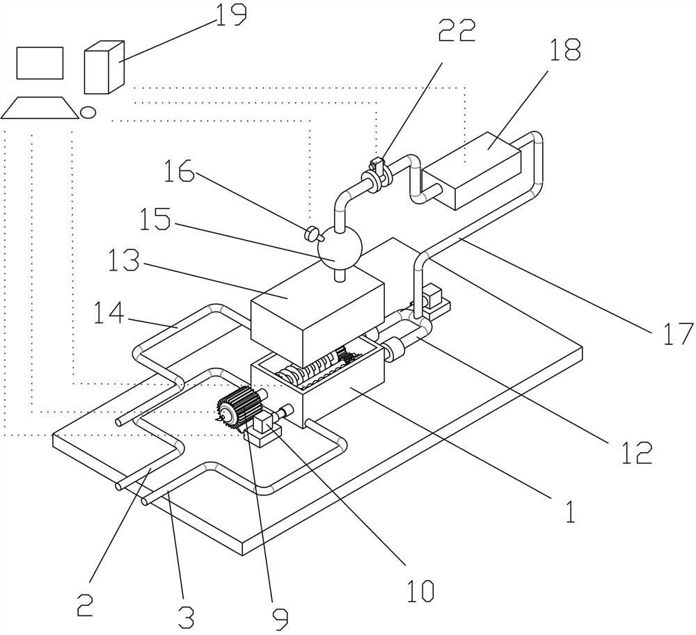
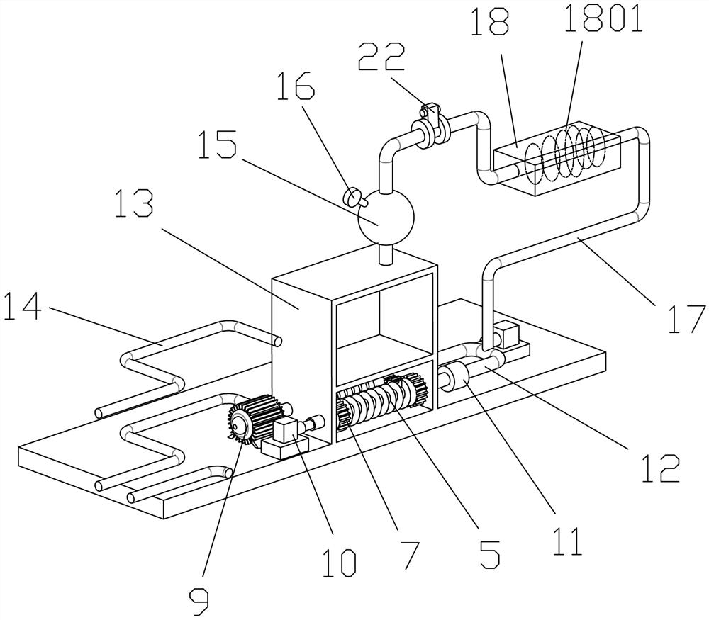
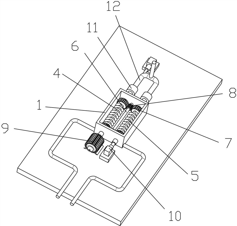
[0031] Such as Figure 1 to Figure 3 As shown, a bitumen steam thermal cycle foaming system includes a stirring device part and a steam device part, the stirring device includes a stirring box 1, and the stirring box 1 is provided with a first stirring rod 4 and a second stirring rod 5 for stirring Asphalt, the center line of the mixing tank 1 is provided with a connecting rod 6, the first stirring rod 4 and the second stirring rod 5 are respectively arranged on both sides of the connecting rod 6 in a symmetrical distribution, and the front and rear ends of the stirring rod are fixedly connected with transmission gears 7, The two ends of the connecting rod 6 are fixedly connected with a driven gear 8, the driven gear 8 drives the connecting rod 6 to rotate around the axis of the connecting rod 6, the transmission gear 7 drives the stirring rod to rotate around the axis of the stirring rod, and the first stirring rod 4 , between the second stirring rod 5 and the connecting rod ...


PUM


Abstract

The invention provides an asphalt steam thermal cycle foaming system. According to the asphalt steam thermal cycle foaming system, stirring rods and a connecting rod are arranged in a stirring box, the stirring rods are arranged on the two sides of the connecting rod respectively to be in symmetrical distribution, the stirring rods and the connecting rod are in meshing transmission through transmission gears and driven gears at the two ends, the first stirring rod is connected with a motor, a gas inlet pipe and an electric hydraulic machine, the second stirring rod is connected with the electric hydraulic machine and the gas inlet pipe, the two sides of the bottom of the stirring box are provided with a material feeding pipe and a material discharge pipe, the top of the stirring box is connected with a water tank, the side face of the bottom of the water tank is provided with a water inlet pipe, the top of the water tank is provided with a gas collecting ball tank, the gas collecting ball tank is provided with a barometer, a gas conveying pipe penetrates through a heating box to be connected with the gas collecting ball tank and the gas inlet pipe, an electronic valve is arranged between the gas collecting ball tank and the heating box, and the gas inlet pipe and the stirring rods are connected through rotating couplers. By means of the asphalt steam thermal cycle foaming system, accurate proportioning of asphalt and water can be realized, water vapor and the asphalt can be stirred more uniformly, the foaming quality of the asphalt is improved, and waste of energy is reduced.

Description

technical field [0001] The invention relates to the field of asphalt production and processing, in particular to an asphalt steam thermal cycle foaming system. Background technique [0002] Foamed asphalt is a new material that adds water droplets to high-temperature asphalt to form steam bubbles, which produces a chain reaction and significantly improves the bonding performance. The viscosity and polymerization of foamed asphalt are stronger than ordinary asphalt, and foamed asphalt can be stored for a long time and can be cold rolled In addition, foamed asphalt has the advantages of energy reduction, green environmental protection, etc., and has attracted extensive attention from the domestic and foreign highway industries. [0003] In the existing asphalt foaming process, the heated asphalt is usually placed in the mixing chamber to mix and foam with air and water droplets. The water outlet of the existing foaming device is usually fixed, and the water droplets are contin...

Claims


Application Information

Patent Timeline
Patent Type & Authority Applications(China)
IPC IPC(8): B29C44/34B29C44/60B29K95/00
CPCB29C44/3442B29C44/3415B29C44/60B29K2095/00
Inventor 何明王军黑保江姜归鹤陈志勇柳文星
Owner YICHANG JIANGXIA MARINE MACHINERY
Why Eureka
Try Eureka