
Liquid-gas separable liquid rocket engine multi-layer active cooling device

A technology of rocket engines and liquid rockets, which is applied in the direction of rocket engine devices, machines/engines, jet propulsion devices, etc., can solve problems such as unbearable, unable to guarantee cooling uniformity, unfavorable coolant action time, etc., to ensure stability and Safety, stable and uniform cooling effect, and the effect of prolonging the effective working time

Active Publication Date: 2022-05-13
TIANJIN UNIV
View PDF6 Cites 0 Cited by
  • Summary
  • Abstract
  • Description
  • Claims
  • Application Information

AI Technical Summary

Problems solved by technology

At present, the two commonly used processing methods of cooling pipes include milling groove type and welded tube bundle type, among which the milling groove type cooling pipe is not conducive to ensuring the action time of the coolant, and at the same time has a great impact on the overall strength, and cannot guarantee the uniformity of cooling; The welded tube bundle type has extremely high requirements on the processing technology. With the change of the cross-sectional area of ​​the nozzle, it is necessary to process a variable-diameter pipe. At the same time, the thin-walled structure cannot withstand the high pressure of the active cooling coolant, and the ability to withstand the change of phase change pressure is even greater. weak
[0006] At present, regenerative active cooling technology has been partially applied to scramjet engines, but it is still in the basic research stage in the fields of heat transfer and reaction kinetics, and no relevant patents have been reported at present, and there are relatively few application reports on related equipment. limited
At the same time, research on the application of this technology on rockets is quite limited

Method used

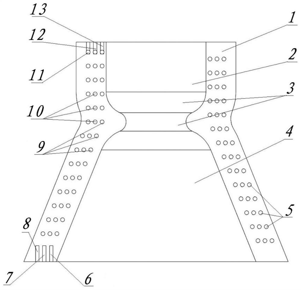
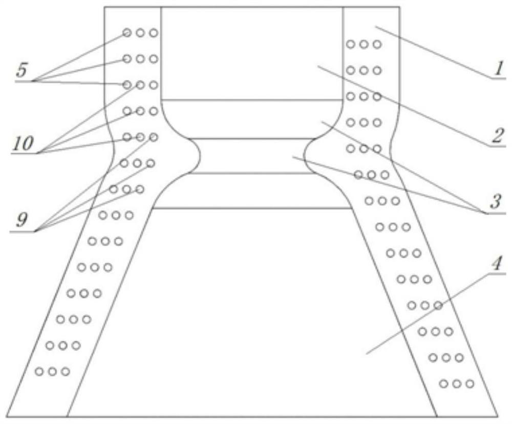
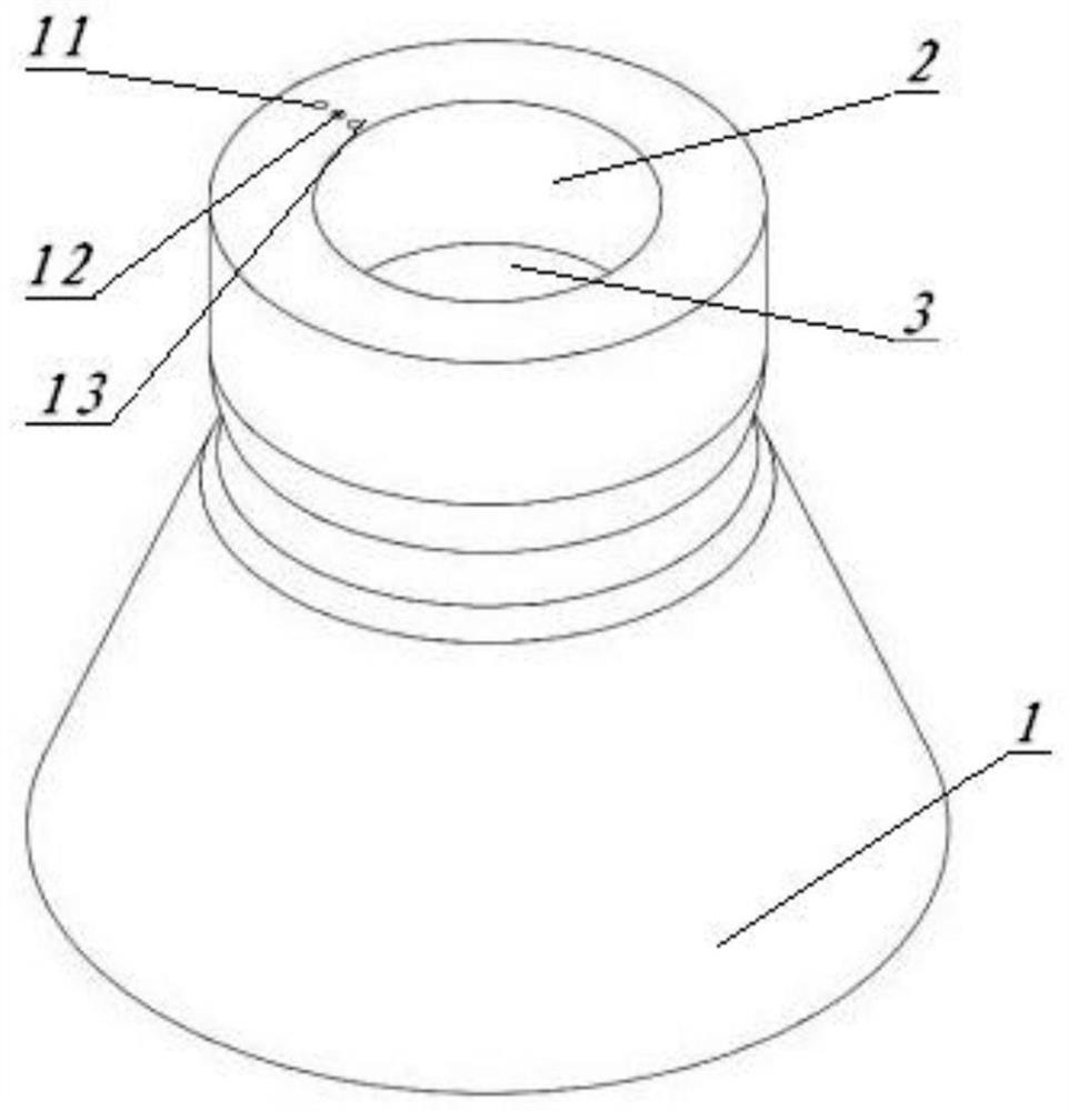

Image

  • Liquid-gas separable liquid rocket engine multi-layer active cooling device
  • Liquid-gas separable liquid rocket engine multi-layer active cooling device
  • Liquid-gas separable liquid rocket engine multi-layer active cooling device

Examples


Embodiment 1

[0041] Such as figure 1 , figure 2 with image 3 As shown, in the present invention, there are three sets of embedded cooling flow pipes for transmitting coolant (coolant is self-carrying fuel in active cooling) (i.e. inner spiral cooling flow pipe 9, middle spiral cooling flow pipe tube 10 and outer layer spiral cooling flow tube 5); each group of embedded spiral cooling flow tubes is an embedded spiral cooling flow tube with a small pitch and the number of spiral nodes is 14-16; the coolant of each embedded spiral cooling flow tube The inlet and the outlet are respectively arranged on the end face of the stave 1 located at the end of the rocket engine nozzle 2 and the end face of the end of the rocket engine combustion chamber 2, and the inlet and the outlet are formed by subtractive machining directly from the outer end face in the vertical direction. , and both are embedded straight pipes intersecting with the respective corresponding embedded spiral cooling flow pipes;...

Embodiment 2

[0051] The working process of using the device of the present invention for active cooling of liquid rockets is as follows:

[0052] In view of the rocket's short working time, one-time work, and extreme harsh working environment, the cooling device has started to work before the rocket is launched. After the safety inspection, the filter 15 with the fuel pump and the shut-off valve opens the shut-off valve, the shut-off valve 16 behind the diverter is opened, the sensing execution and electronic control unit 21 starts to work, and the fuel rail pressure sensor 17, Divider fuel temperature and pressure sensor 18, inner spiral cooling flow pipe pressure sensor 22, middle spiral cooling flow pipe pressure sensor 24, outer spiral cooling flow pipe pressure sensor 23, liquid-gas separator outflow fuel pressure sensor 25 and combustion chamber Corresponding sensors, etc., filter 15 with fuel pump and shut-off valve, splitter fuel pump 20, liquid-gas separator outflow fuel pump 26, ga...


PUM


Abstract

The invention discloses a multi-layer active cooling device for a liquid rocket engine capable of separating liquid and gas, comprising a cooling device, a supporting oil circuit, a gas circuit and a signal transmission device; Three-stage spiral cooling flow tubes are embedded from the inside to the outside; the three-stage spiral cooling flow tubes are all helical and have equal pitch, the number of nodes is 14-16, the radial arrangement is uniform, the spacing is equal, and they are independent of each other; They are respectively connected to the three inlets and three outlets on the two end faces of the cooling wall; the supporting oil circuit, air circuit and signal transmission device include the pressure-stabilizing oil rail, filter, liquid Gas separator and gas storage device. The design of the three-stage spiral embedded flow tube in the present invention is suitable for the one-time use of rocket cooling equipment, can effectively increase the working time of the cooling equipment, and delay the overall failure of the cooling device. The device is safe and reliable, and matches with the current development direction of processing technology.

Description

technical field [0001] The invention relates to the technical field of anti-heat insulation devices for aerospace launches, and relates to an active cooling device for liquid rocket engines that uses three-stage spiral embedded flow tubes for cooling, especially relates to an active cooling device for liquid rocket engines, with its own Liquid-gas separation device and an active cooling device that uses three-stage spiral embedded flow tubes for cooling. Background technique [0002] The instantaneous temperature of aerospace vehicles such as rockets and space shuttles will reach 3000-4000K when they are ignited. Depending on the flow field, the type of fuel used, and the specific chemical reaction conditions, the local temperature may be higher. Flames and gas streams have temperatures well in excess of the melting temperatures of most common metals and alloys, causing rapid failure of combustor devices and cooling devices. Therefore, an effective cooling scheme is extreme...

Claims


Application Information

Patent Timeline
Patent Type & Authority Patents(China)
IPC IPC(8): F02K9/60F02K9/64F02K9/54F02K9/56F02K9/97
CPCF02K9/60F02K9/64F02K9/54F02K9/56F02K9/97
Inventor 贺泳迪夏然宋金瓯
Owner TIANJIN UNIV
Learn More