
Real-time displacement reconstruction method and device

A displacement and laser technology, applied in measurement devices, optical devices, instruments, etc., can solve the problems of large reconstruction error, inaccurate reverse points, and increased equipment costs, so as to improve displacement measurement accuracy and avoid jump points. Loss, avoids the effect of measurement errors

Active Publication Date: 2021-05-04
NORTHEAST GASOLINEEUM UNIV
View PDF5 Cites 2 Cited by
  • Summary
  • Abstract
  • Description
  • Claims
  • Application Information

AI Technical Summary

Problems solved by technology

[0003] In the existing laser self-mixing displacement measurement technology, two methods are usually used for displacement reconstruction. The first method is the external cavity phase modulation method. This method requires the introduction of an electro-optic modulator in the external cavity, which greatly increases the cost of the entire experimental equipment.
The second is to use the demodulation algorithm to reconstruct the displacement of the target vibrating object. In the process of reconstructing the displacement, it is necessary to manually select points for the signal, resulting in large reconstruction errors and poor real-time performance.
However, in the prior art, in order to obtain two phase-orthogonal self-mixing signals, complex algorithms are required to process the collected self-mixing signals. The more typical method is the self-mixing interferometric vibration measurement method based on Hilbert transform. However, this method needs to manually select the inversion point. On the one hand, the selection of the inversion point is not accurate enough, which leads to a large reconstruction error at the peak point when the method reconstructs the displacement. On the other hand, it is impossible to realize the All processing programs are integrated into the software, and real-time displacement reconstruction is impossible. The real-time performance is poor, and it is difficult to realize real-time measurement of vibration displacement.
The algorithms used in the prior art are relatively complex and require high signal quality. If the signal quality at the reverse point is poor, the reconstruction error will increase
In addition, when the Hilbert transform is performed on the signal, the Hilbert transform is aimed at an infinite-length sequence, and when applied to a finite-length sequence, it will also bring a certain error
To sum up, in the prior art, if no expensive external equipment is used to reconstruct the displacement, the reconstruction error will be larger, and the cost of reconstructing the displacement with expensive external equipment is higher

Method used


Image

  • Real-time displacement reconstruction method and device
  • Real-time displacement reconstruction method and device
  • Real-time displacement reconstruction method and device

Examples


specific Embodiment

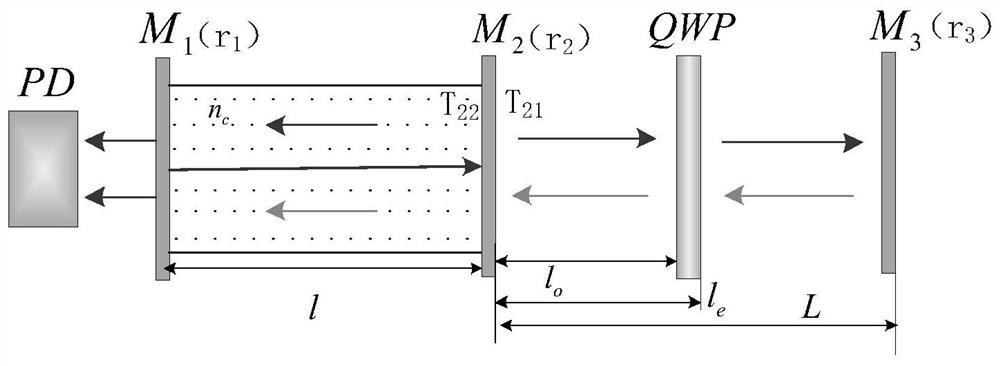
[0052] figure 1 A three-mirror cavity theoretical model of a real-time displacement reconstruction device according to an embodiment of the present disclosure is shown. like figure 1 as shown, r 1 and r 2 are two laser cavity surfaces M 1 , M 2 The reflection coefficient of , corresponding to the experimental setup image 3 In the two cavity faces of the laser, T 21 from lumen M 2 Transmission coefficient to the external cavity, T 22 is from the outer cavity to the inner cavity M 2 The transmission coefficient of r 3 is the amplitude reflection coefficient of the external feedback mirror, l is the cavity length of the laser, L is the length of the external cavity, l λ / 4 The optical path l introduced for the quarter wave plate λ / 4 = l o -l e . no c is the complex refractive index of the laser cavity material, and k is the wave vector.

[0053]

[0054] When the quarter-wave plate is introduced into the external cavity, the polarization directions of the two b...


PUM


Abstract

The invention discloses a real-time displacement reconstruction method and device. The main objective of the invention is to solve a problem that real-time displacement reconstruction cannot be performed on two paths of phase-orthogonal self-mixing signals obtained based on Hilbert transform in an existing self-mixing interference vibration measurement method. The method is characterized by comprising the following steps: generating a self-mixing interference signal based on a first optical signal emitted by a laser and a second optical signal returned by a first object; acquiring two paths of orthogonal self-mixing signals through an attenuation sheet, a polaroid, a spectroscope, a wave plate and a polarization spectroscope; carrying out filtering normalization processing on the two paths of orthogonal self-mixing signals; and dividing the two paths of normalized orthogonal self-mixing signals, carrying out arc tangent transformation, carrying out unwrapping processing, and carrying out displacement reconstruction in real time. The method is high in measurement precision, and meanwhile, real-time displacement reconstruction can be realized after programmed processing is carried out on data by combining a computer.

Description

Technical field: [0001] The invention relates to the field of vibration detection, in particular to a real-time displacement reconstruction method and device applied to an optical interferometer. Background technique: [0002] Laser self-mixing interference means that in a laser application system, after the light output by the laser is reflected or scattered by an external object, part of the light is fed back to the resonant cavity of the laser. The feedback light carries the information of the external object, and after mixing with the light in the cavity, the output power and frequency of the laser are modulated to form laser self-mixing interference. Compared with traditional optical interferometry, the use of laser self-mixing interferometry to measure vibration source information has the advantages of simple optical path, easy alignment, and compact structure. Laser self-mixing interferometry technology has been widely used in displacement, vibration, distance, speed ...

Claims


Application Information

Patent Timeline
Patent Type & Authority Applications(China)
IPC IPC(8): G01B11/02G01B9/02
CPCG01B11/02G01B9/02092
Inventor 董太极高丙坤姜春雷王秀芳陈朋梁洪卫
Owner NORTHEAST GASOLINEEUM UNIV
Learn More