Rotary basket continuous countercurrent extraction device
A countercurrent extraction and basket-rotating technology, applied in solvent extraction, solid solvent extraction, chemical instruments and methods, etc., can solve the problems of inability to use vertical extraction tanks, low work efficiency, and easy leakage.
- Summary
- Abstract
- Description
- Claims
- Application Information
AI Technical Summary
Problems solved by technology
Method used
Image
Examples
no. 1 example
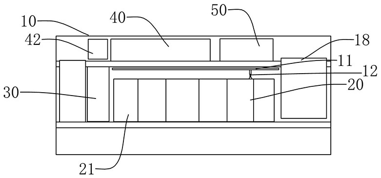
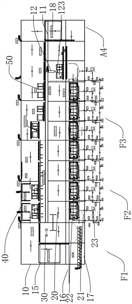
[0031] Such as Figure 1 to Figure 3 As shown, the present invention provides a continuous countercurrent extraction device with a rotating basket, which includes a casing 10, in which an extraction area 20, an overturning slag discharge area 30, a cleaning area 40, and a feeding area 50 are sequentially arranged. 10 is also provided with a track 11 on which a manipulator 12 is arranged, and the track 11 is set above the extraction area 20 , the turning and slag discharge area 30 , the cleaning area 40 and the feeding area 50 .
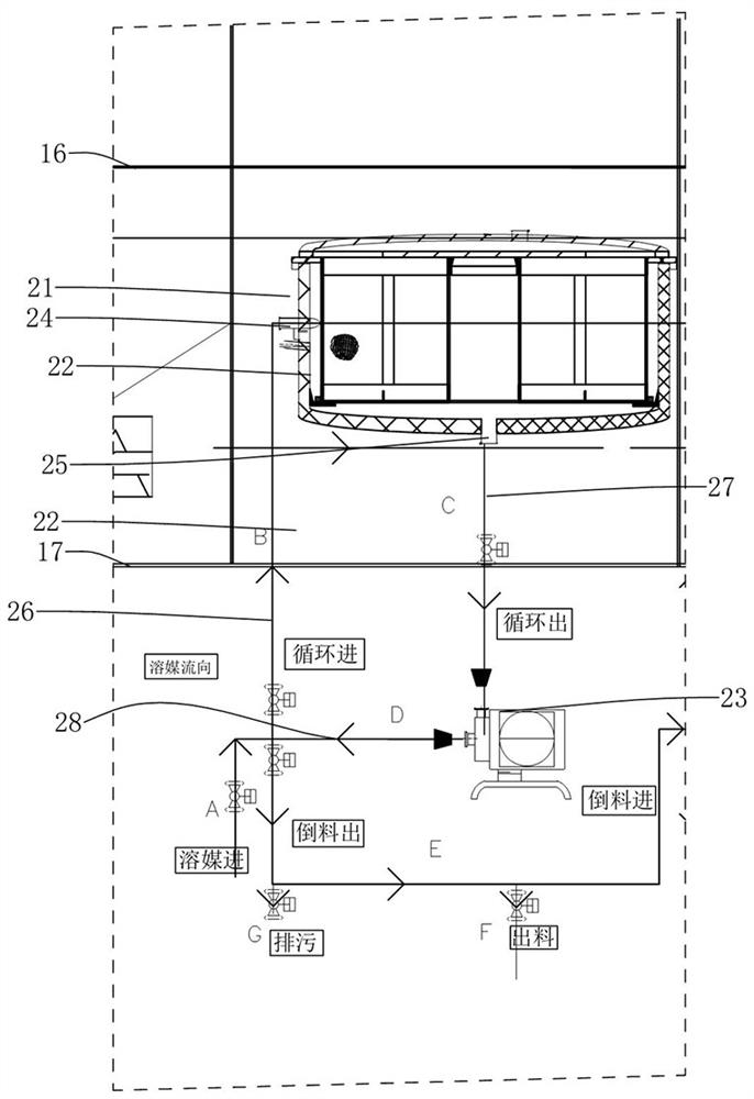
[0032] which, combined with Figure 4 As shown, the extraction zone 20 includes a plurality of extraction units 21 connected in series, the extraction unit 21 includes an extraction tank 22 and a circulation pump 23, the extraction tank 22 has a side wall inlet 24 and a bottom outlet 25, and the side wall inlet 24 is connected to the first solvent inflow pipe 26, the bottom outlet 25 is connected to the circulation pump 23 through the solvent outflow...
no. 2 example
[0045] As a preferred solution, such as Figure 5 to Figure 8 As shown, a first layer platform 15 , a second layer platform 16 and a third layer platform 17 are sequentially arranged in the casing 10 of this embodiment from top to bottom. The cleaning area 40 and the feeding area 50 are arranged on the first layer platform 15, and the second layer platform 16 has the first side tray elevator 18, the basket conveying track 11, the turning and slag discharge area 30 and the second side tray elevator 19 in sequence, And the first side tray lifter 18 is connected to the feeding area 50 through the first buffer zone 41 , while the second side tray lifter 19 is connected to the cleaning zone 40 through the second buffer zone 42 .
[0046] In the specific use process: when transferring from the feeding area 50 of the first floor platform 15 to the second floor platform 16, the medicine basket 123 is placed on the first side tray elevator 18, and passes through the first side tray Th...
no. 3 example
[0050] Manipulator 12 of the present invention is existing structure, and as preferred scheme, Figure 9 As shown, this embodiment provides one of the manipulator structures. The clamping and rotating manipulator includes a connected clamping part 121 and a rotating part 122. The clamping part 121 is used to clamp the medicine basket 123, and the rotating part 122 is used to drive the medicine basket. 123 flips. In the specific use process, the clamping action for the medicine basket 123 is completed by the clamping member 121, and then the rotating member 122 drives the clamping member 121 to rotate, generally the medicine basket 123 is rotated 180°, so that the medicine basket 123 The opening of the medicine basket is downward, so that the medicine dregs can be completely separated from the medicine basket 123, and the medicine basket 123 is placed in a reversed state, so that the subsequent cleaning process will become easier. The clamping and rotating manipulator can pref...
PUM
 Abstract
Description
Claims
Application Information
 - R&D
- Intellectual Property
- Life Sciences
- Materials
- Tech Scout
- Unparalleled Data Quality
- Higher Quality Content
- 60% Fewer Hallucinations
Browse by: Latest US Patents, China's latest patents, Technical Efficacy Thesaurus, Application Domain, Technology Topic, Popular Technical Reports.
© 2025 PatSnap. All rights reserved.Legal|Privacy policy|Modern Slavery Act Transparency Statement|Sitemap|About US| Contact US: help@patsnap.com


