
Drying room of circular screen printer

A technology for printing machines and drying rooms, which is applied to general parts of printing machines, printing machines, printing, etc., can solve the problems of energy waste, uneven heating of the upper and lower surfaces of the fabric, and unfavorable production and processing of high-quality products. Avoid energy loss and improve the effect of drying area

Inactive Publication Date: 2021-05-07
FUJIAN JINJIANG JILONG MACHINE IND
View PDF9 Cites 0 Cited by
  • Summary
  • Abstract
  • Description
  • Claims
  • Application Information

AI Technical Summary

Problems solved by technology

[0002] The drying room is the drying equipment of the rotary screen printing machine. After the fabric is printed and dyed by the rotary screen, the color paste on the fabric is still in a liquid or partially liquid-solid mixed state. The final product requires the color paste to be embedded in the surface of the fabric in a solid state. This requires the drying room to quickly solidify the color paste by means of high temperature and high pressure. The existing drying room can only blow air to the fabric in one direction, resulting in uneven heating of the upper and lower surfaces of the fabric, which is not conducive to production and processing of high-quality fabrics. At the same time, the heat generated by the drying room is often directly discharged into the atmosphere, resulting in a waste of energy

Method used


Image

  • Drying room of circular screen printer
  • Drying room of circular screen printer
  • Drying room of circular screen printer

Examples


Embodiment Construction

[0014] The present invention will be described in further detail below in conjunction with the accompanying drawings.

[0015] The specific implementation manner of the present invention will be further described below in conjunction with the accompanying drawings. Wherein the same components are denoted by the same reference numerals. It should be noted that the words "front", "rear", "left", "right", "upper" and "lower" used in the following description refer to the directions in the drawings, and the words "inner" and "outer ” refer to directions towards or away from the geometric center of a particular part, respectively.

[0016] In order to make the content of the present invention more clearly understood, the technical solutions in the embodiments of the present invention will be clearly and completely described below in conjunction with the drawings in the embodiments of the present invention.

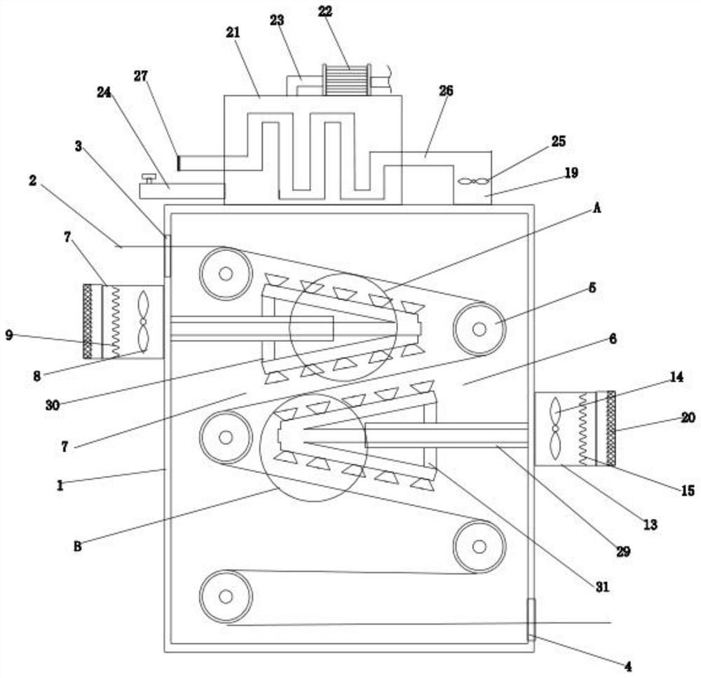
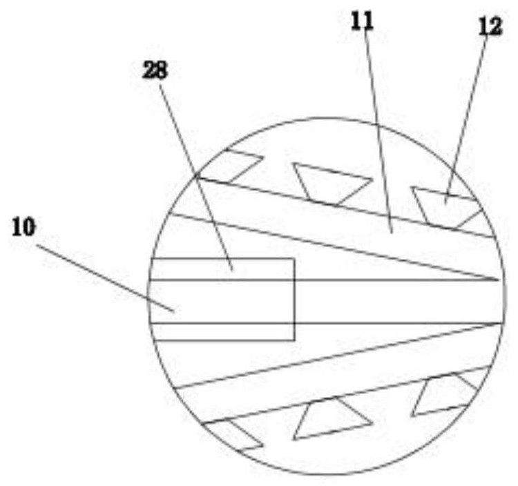
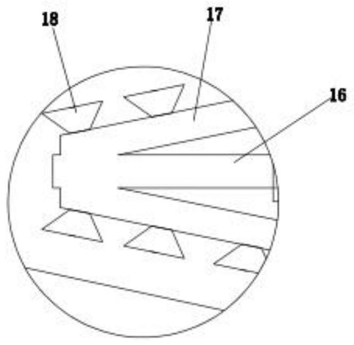
[0017] combined with Figure 1-3 , a drying room of a rotary screen pri...


PUM


Abstract

The invention discloses a drying room of a circular screen printer. The drying room comprises a drying room body and a fabric, a cloth inlet and a cloth outlet are correspondingly formed in the two ends of the drying room body, a plurality of cloth guide rollers are rotatably arranged on the drying room body, and the fabric divides an inner chamber of the drying room body into a fabric lower surface drying area and a fabric upper surface drying area. A first air inlet box is arranged on the side wall of the drying room body, a first air inlet fan and a first heating wire are arranged in the first air inlet box, a first air outlet header pipe is arranged at the air outlet end of the first air inlet box, a first air outlet branch pipe oppositely communicates with the first air outlet header pipe, a second air inlet fan and a second heating wire located at the outer end of the second air inlet fan are arranged in the second air inlet box, a second air outlet header pipe is arranged at the air outlet end of the second air inlet box, a second air outlet branch pipe oppositely communicates with the second air outlet header pipe, a second air outlet cover is arranged on the second air outlet branch pipe, and an exhaust pipe is arranged above the drying room body. Compared with the prior art, the drying room of the circular screen printer has the advantages that waste of heat energy is avoided, and the upper surface and the lower surface of the fabric can be dried at the same time.

Description

technical field [0001] The invention relates to the technical field of rotary screen printing machines, in particular to a drying chamber of a rotary screen printing machine. Background technique [0002] The drying room is the drying equipment of the rotary screen printing machine. After the fabric is printed and dyed by the rotary screen, the color paste on the fabric is still in a liquid or partially liquid-solid mixed state. The final product requires the color paste to be embedded in the surface of the fabric in a solid state. This requires the drying room to quickly solidify the color paste by means of high temperature and high pressure. The existing drying room can only blow air to the fabric in one direction, resulting in uneven heating of the upper and lower surfaces of the fabric, which is not conducive to production and processing of high-quality fabrics. At the same time, the heat generated by the drying room is often directly discharged into the atmosphere, resu...

Claims


Application Information

Patent Timeline
IPC IPC(8): B41F23/04B01D53/04F28D7/08
CPCB41F23/0426B01D53/0407F28D7/082B01D2253/102
Inventor 陈凡翁少华肖石发
Owner FUJIAN JINJIANG JILONG MACHINE IND
Features
  • Generate Ideas
  • Intellectual Property
  • Life Sciences
  • Materials
  • Tech Scout
  • Unparalleled Data Quality
  • Higher Quality Content
  • 60% Fewer Hallucinations
Learn More