Squirrel-cage squeeze film damper

A technology of squeezing oil film damping and damper, applied in the direction of spring/shock absorber, ball bearing, vibration suppression adjustment, etc., can solve the problems of complex structure, difficult control of stiffness and high production cost

Active Publication Date: 2021-05-07
DALIAN UNIV OF TECH
View PDF12 Cites 0 Cited by
  • Summary
  • Abstract
  • Description
  • Claims
  • Application Information

AI Technical Summary

Problems solved by technology

[0004] The present invention provides a squirrel-cage squeeze oil film damper in order to solve the problems of complex structure, high production cost and difficult rigidity control of the existing squeeze oil film damper

Method used


Image

  • Squirrel-cage squeeze film damper
  • Squirrel-cage squeeze film damper
  • Squirrel-cage squeeze film damper

Examples


specific Embodiment approach 1

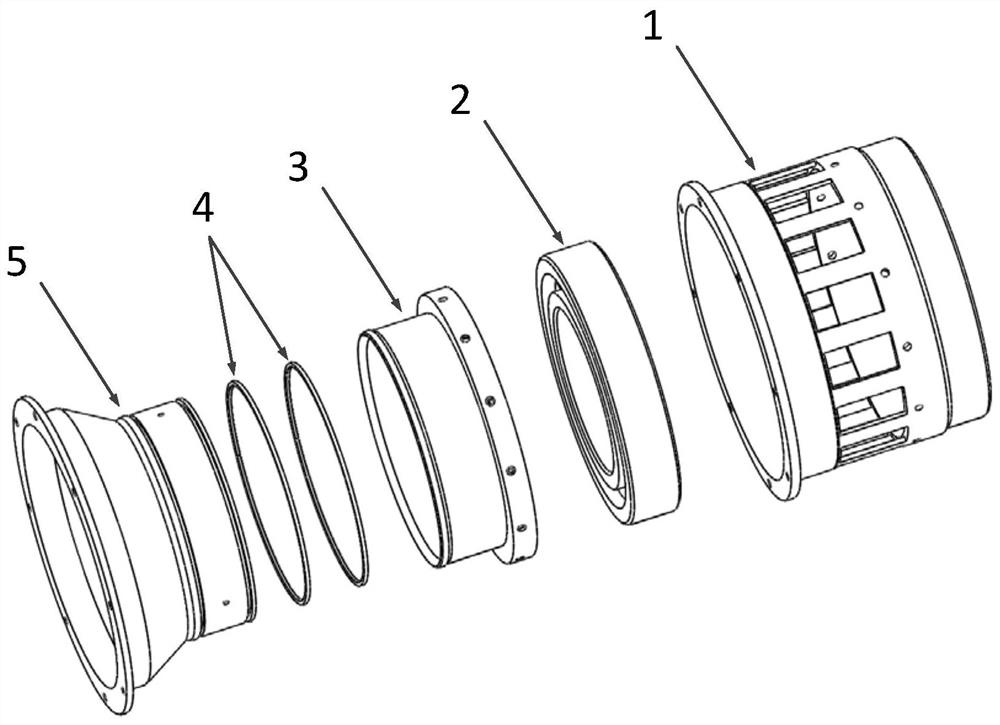
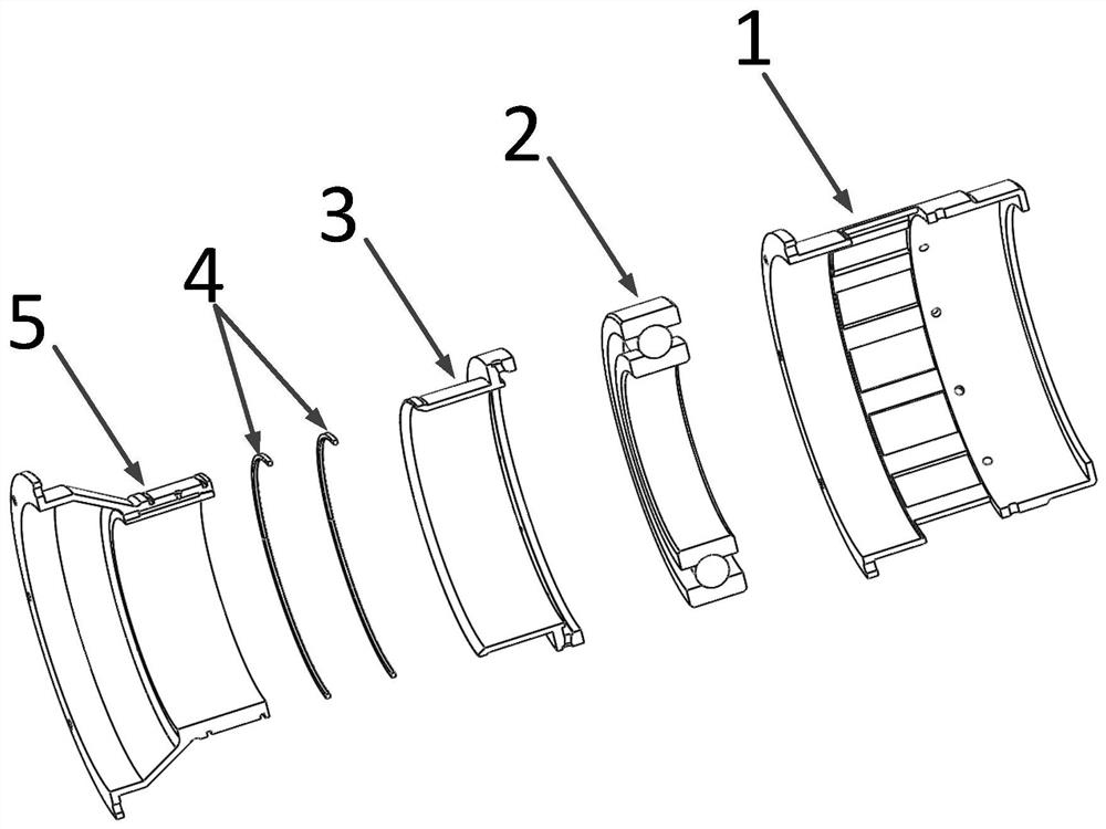
[0039] Specific implementation mode 1: The specific implementation mode of the present invention will be further described below in conjunction with accompanying drawings 1 to 8 .

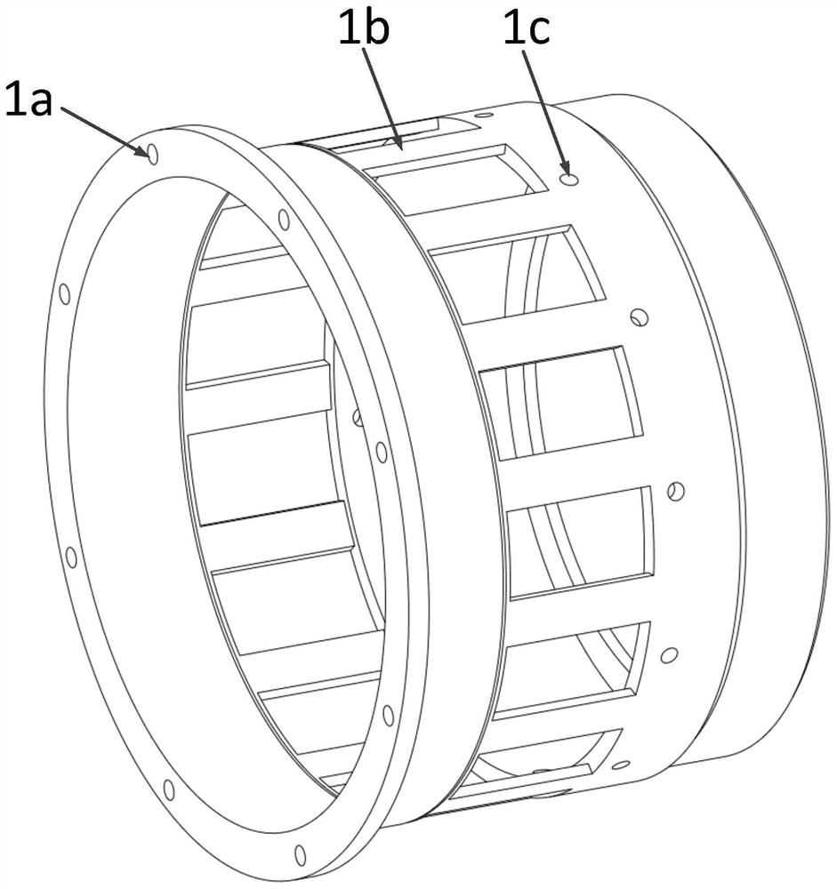
[0040] As shown in Figure 1, a squirrel-cage squeeze oil film damper includes a squirrel-cage housing 1, a bearing 2, a damper outer sleeve 3, a sealing ring 4, and a damper inner sleeve 5; wherein, as shown in Figure 2, The squirrel cage housing 1 generally looks like a hollow cylinder, one end of which is a flange with a threaded hole 1a. The middle part is not completely closed, and is composed of several cage bars 1b. The number, length, width and thickness of the cage bars 1b can be designed according to the needs of the actual support stiffness. Many oil return holes 1c are evenly opened on the squirrel cage housing 1, and the number of oil return holes 1c is designed according to actual needs. The inner diameter of the other end of the squirrel cage housing 1 is slightly smaller to block th...

specific Embodiment approach 2

[0049] Embodiment 2: The ratio of the inner diameters of the large diameter section of the oil inlet 5b, the small diameter section of the oil inlet 5b, and the bearing oil injection hole 5e is 8:4:1; the large diameter section of the oil inlet 5b, the oil inlet 5b The ratio of the lengths of the small-diameter section 5b and the oil injection hole 5e of the bearing is 1:4:1. The oil leakage hole 3a on the outer sleeve of the damper is inclined away from the axial direction of the bearing when viewed from the oil inlet to the oil outlet. In the squirrel cage housing 1, the through holes between adjacent cage bars 1b are rectangular through holes, and the length of the rectangular through holes is 1 / 3rd of the overall length of the squirrel cage housing 1; the width of each rectangular through hole is It is twice the width of the cage bar between adjacent rectangular through holes. The included angle between the axis of the oil injection hole 5e of the bearing and the axis of ...


PUM


Abstract

The invention discloses a squirrel-cage squeeze film damper, and belongs to the technical field of squeeze film dampers. The squirrel-cage squeeze film damper aims to solve the problems that an existing squeeze film damper is complex in structure and high in production cost, and the rigidity is not easy to control. The squirrel-cage squeeze film damper comprises a squirrel-cage shell, a bearing, a damper sleeve assembly and a lubricating oil way, wherein the damper sleeve assembly and the bearing are arranged in the squirrel-cage shell, the damper sleeve assembly is attached to the bearing, the damper sleeve assembly is provided with the lubricating oil way for lubricating the bearing and an oil ring cavity, and the lubricating oil way is in communication with the oil ring cavity. According to the squirrel-cage squeeze film damper, the vibration phenomenon of a rotating shaft system can be reduced, the design flexibility and installation convenience of the squeeze film damper are improved, and the production cost is reduced; and the damper is simple in structure, convenient to install and low in manufacturing cost, the supporting rigidity of the damper is easier to control, and the rigidity can be changed only by changing the number, the length, the thickness or the width of the squirrel cage bars.

Description

technical field [0001] The invention belongs to the technical field of dampers, in particular to a squirrel-cage squeeze oil film damper. Background technique [0002] When the rotating shaft of a rotating machine is running at high speed, it often passes through the critical speed of the shaft system. When the rotating shaft passes through the critical speed, system resonance will occur. This phenomenon will cause excessive vibration of the shaft system and greater noise from the entire equipment. The fracture of the rotating shaft will cause serious accidents and cause huge loss of personnel and property. Therefore, it is very necessary to reduce the vibration of the rotating shaft system of the rotating machine. At present, the most commonly used is to use the squeeze oil film damper for vibration reduction. The squeeze oil film damper is an extremely important supporting component in modern high-speed rotating machinery. It has a wide range of applications, from ground g...

Claims


Application Information

Patent Timeline
Patent Type & Authority Applications(China)
IPC IPC(8): F16F15/023F16C19/16
CPCF16C19/16F16F15/023F16F15/0237
Inventor 徐方程栾雯霖候留凯
Owner DALIAN UNIV OF TECH
Why Eureka
Try Eureka