Supercharge Your Innovation With Domain-Expert AI Agents!

Plasma melting furnace device based on flue circular heating

A circulating heating and plasma technology, which is applied in lighting and heating equipment, incinerators, combustion methods, etc., can solve the problems of abnormal material discharge, large temperature difference between the upper and lower sides of the magma, and easy solidification, so as to improve fluidity and high-efficiency utilization , the effect of easy nesting

Pending Publication Date: 2021-05-07
重庆新离子环境科技有限公司
View PDF0 Cites 0 Cited by
  • Summary
  • Abstract
  • Description
  • Claims
  • Application Information

AI Technical Summary

Problems solved by technology

The main disadvantages are: (1) Only the liquid surface of the molten material can accept the heat conduction and heat radiation of the plasma torch, while the heat absorption under the liquid surface of the molten material is insufficient, and it is difficult to melt the material below the liquid surface only by the heat conduction of the magma itself. Therefore, the thermal efficiency of the furnace is relatively low
(2) The material openings of the plasma furnace are all located at the bottom of the furnace, and the magma flows out of the furnace by its own fluidity. The temperature difference between the upper and lower sides of the magma is large, the melting effect of the magma at the bottom is poor, and it is easy to solidify, which leads to abnormal discharge.
(3) The existing plasma melting furnace is operated under negative pressure, which causes a part of the high-temperature flue gas of the plasma torch to be taken away by the negative pressure in the furnace and enter the flue directly, so the temperature of the furnace cover and the flue is seriously exceeded. However, the temperature is very low, resulting in "the top burns fiercely, but the bottom is cold", which seriously affects the use of the plasma furnace, which not only wastes the heat of high-temperature flue gas, but also seriously affects the service life of the furnace cover.

Method used


Image

  • Plasma melting furnace device based on flue circular heating
  • Plasma melting furnace device based on flue circular heating
  • Plasma melting furnace device based on flue circular heating

Examples


Embodiment Construction

[0023] The present invention will be described in detail below in conjunction with the accompanying drawings and specific embodiments.

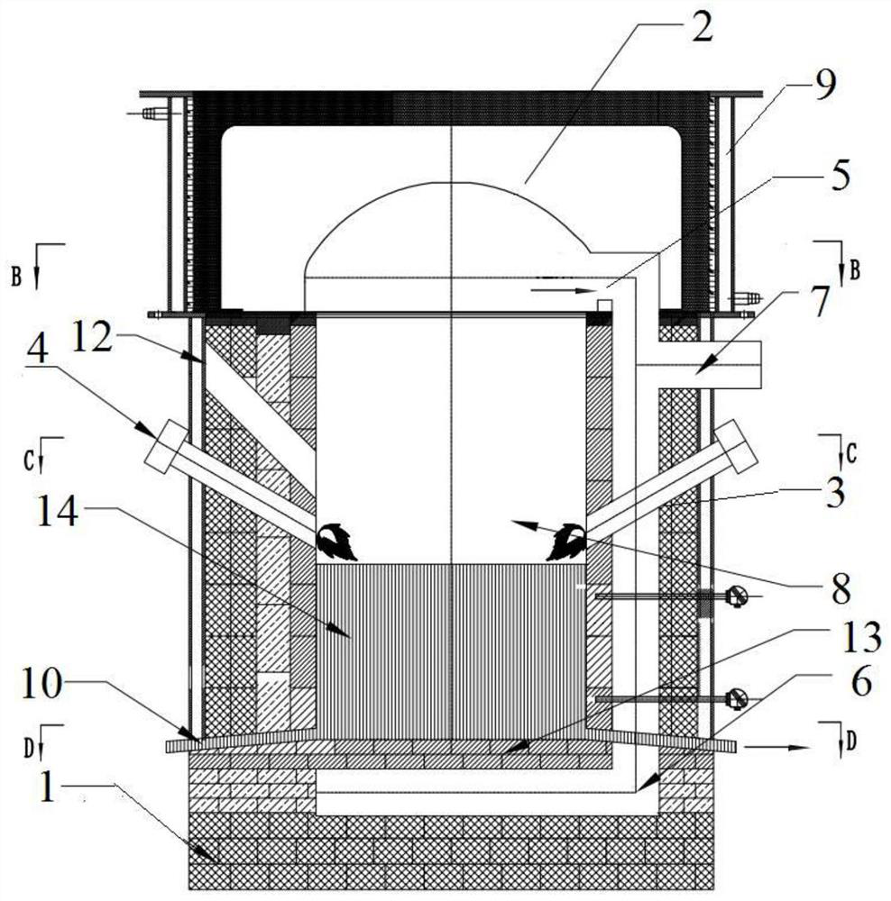
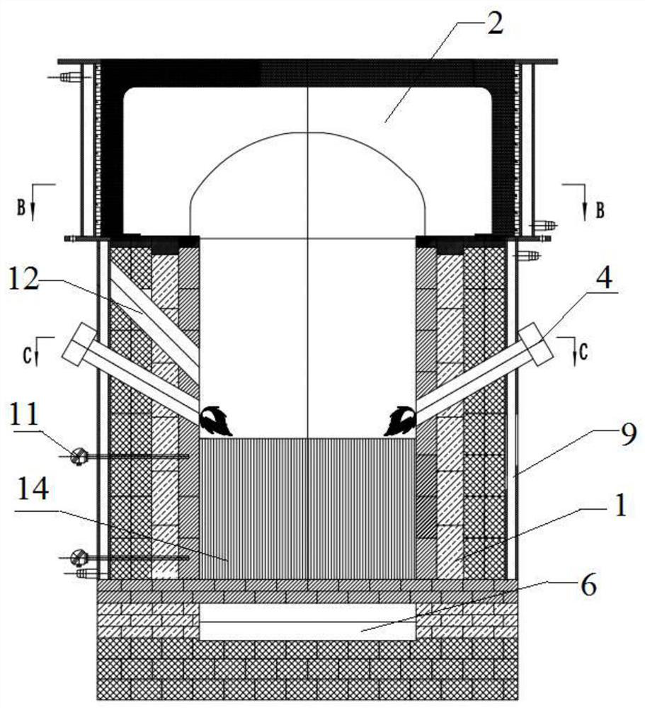
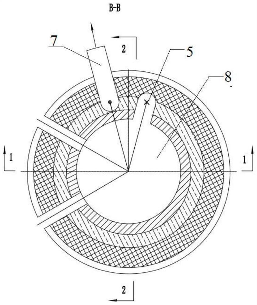
[0024] A kind of plasma melting furnace device based on flue circulation heating of the present invention, such as figure 1 and figure 2 As shown, a furnace body 1 is included, and the furnace body 1 is sealed and connected to the furnace cover 2 to form a furnace hearth 8. A plurality of plasma torch channels 3 inclined downward from the outside to the inside are opened in the side wall of the furnace body 1, and each plasma torch channel 3 The plasma torch 4 is internally connected, the furnace cover 2 is provided with a smoke inlet passage 5, the furnace wall of the furnace body 1 is provided with a circulating high-temperature flue 6 connected to the smoke inlet passage 5, and the outer wall of the furnace body 1 is provided with an exhaust pipe connected with the circulating high-temperature flue 6. The smoke port 7 also includes a dis...


PUM


Abstract

The invention discloses a plasma melting furnace device based on flue circular heating. The plasma melting furnace device comprises a furnace body, the furnace body is connected with a furnace cover in a sealed mode to form a hearth, a plurality of plasma torch channels inclining downwards from outside to inside are formed in the side wall of the furnace body, each plasma torch channel is internally connected with a plasma torch, a smoke inlet channel is formed in the furnace cover, a circulating high-temperature flue communicating with the smoke inlet channel is formed in the furnace wall of the furnace body, and a smoke outlet communicating with the circulating high-temperature flue is formed in the outer wall of the furnace body; and the plasma melting furnace device further comprises a discharging pipe, the discharging pipe penetrates through the side wall of the bottom of the furnace body to communicate with the hearth, and a feeding channel is further formed in the side wall of the furnace body. High-temperature flue gas is guided into the furnace bottom to heat a cold area of the furnace bottom, and efficient utilization of flue gas heat is achieved, so that materials in the hearth are evenly melted, the liquidity of the melted materials is improved, and rapid, simple and convenient discharging is achieved.

Description

technical field [0001] The invention belongs to the technical field of plasma melting furnace equipment, and in particular relates to a plasma melting furnace device based on flue circulation heating. Background technique [0002] The plasma melting furnace is used in the field of hazardous waste disposal, and has many advantages such as wide application range, weight reduction, and harmlessness. The principle is to use a plasma torch as a heat source to melt the reactants to form a non-toxic and harmless glass body. [0003] At present, the existing plasma furnace usually adopts top-inserted and side-inserted plasma torches, and the liquid level of the melt in the furnace is lower than that of the plasma torches. The main disadvantages are: (1) Only the liquid surface of the molten material can accept the heat conduction and heat radiation of the plasma torch, while the heat absorption under the liquid surface of the molten material is insufficient, and it is difficult to ...

Claims


Application Information

Patent Timeline
IPC IPC(8): F23G7/00F23G5/10F23G5/44F23G5/46
CPCF23G5/10F23G5/44F23G5/46F23G7/00F23G2204/201F23G2206/10
Inventor 雷仲波谢庚王卫民王山孙毅晨吴忠勇陶应翔
Owner 重庆新离子环境科技有限公司
Features
  • R&D
  • Intellectual Property
  • Life Sciences
  • Materials
  • Tech Scout
  • Unparalleled Data Quality
  • Higher Quality Content
  • 60% Fewer Hallucinations
Learn More