In-service integral composite material R area detection method, reference test block and test block manufacturing method

A technology for comparing test blocks and detection methods, applied in the direction of measuring devices, analyzing materials, processing detection response signals, etc., can solve problems such as undetectable in-situ, and achieve the effect of reducing operation and maintenance costs and large-scale engineering application value

Active Publication Date: 2021-05-07
CHENGDU AIRCRAFT INDUSTRY GROUP
View PDF11 Cites 5 Cited by
  • Summary
  • Abstract
  • Description
  • Claims
  • Application Information

AI Technical Summary

Problems solved by technology

Solved the in-situ undetectable problem of delamination defects in

Method used


Image

  • In-service integral composite material R area detection method, reference test block and test block manufacturing method
  • In-service integral composite material R area detection method, reference test block and test block manufacturing method
  • In-service integral composite material R area detection method, reference test block and test block manufacturing method

Examples


Embodiment 1

[0069] This example proposes an ultrasonic phased array sector scan imaging detection method for the R-zone of an in-service integrated composite material, which is used for material detection of the R-zone of an in-service integrated composite material product based on the ultrasonic phased array sector scan imaging technology and product quality evaluation, such as figure 1 , figure 2 , image 3 , Figure 4 , Figure 9 , Figure 10 , Figure 11 , Figure 12 , Figure 13 , Figure 14 , Figure 15 , Figure 16 , Figure 17 , Figure 18 , Figure 19 , Figure 20 , Figure 21 , Figure 22 , Figure 23 , Figure 24 , Figure 25 , Figure 26 , Figure 27 , Figure 28 , Figure 29 , Figure 30 As shown, the R-zone ultrasonic phased array sector scanning imaging detection method of the overall composite material in service includes the following steps:

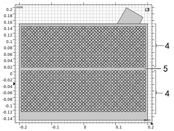
[0070] Step 1: First, establish the ultrasonic phased array detection simulation model of the R zone of t...

Embodiment 2

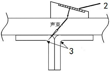
[0089] This example proposes a comparison test block, which is used for the above-mentioned detection method of ultrasonic phased array sector scanning imaging in the R zone of the overall composite material in service, such as Figure 5 , Figure 6 , Figure 7 , Figure 8 , Figure 9 As shown, the comparison test block includes a Z rib part, a C rib part and a panel part made of multi-layer composite material prepreg; the panel part is laid flat on the bottom, and the C rib part and the Z rib part are arranged on the panel part to overlap , and the three together constitute the comparative test block of the J-shaped rib structure;

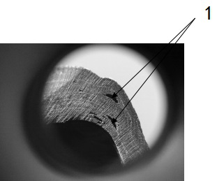
[0090] In the inner layer of the composite material prepreg of the Z rib or / and the R zone of the C rib, artificial defects 8 are placed at dislocation intervals;

[0091] The artificial defect 8 is a double-layer polytetrafluoroethylene circular diaphragm;

[0092] The size of the comparison test block is 190mm×170mm×124mm.

Embodiment 3

[0094] This embodiment proposes a method for manufacturing a comparison test block, which is used to manufacture the above comparison test block, such as Figure 5 , Figure 6 , Figure 7 , Figure 8 , Figure 9 The manufacturing method shown includes the following steps:

[0095] Step S1: produce and design the artificial defect 8, and manufacture a double-layer polytetrafluoroethylene diaphragm with a radius of Φ6mm as the artificial defect 8;

[0096] Step S2: Lay up the test blocks. The specific operation is: use 50 sheets of composite material prepreg with a single layer thickness of 0.125mm and a size of 200mm×200mm to form the panel part; use 14 sheets with a single layer thickness of 0.125mm, Composite prepregs with a size of 280mm×200mm are laid up to form the Z-bar; 14 sheets of composite prepregs with a single layer thickness of 0.125mm and a size of 280mm×200mm are laid up to form the C-bar;

[0097] Step S3: Collage the C-bar part, Z-bar part and panel part, ...


PUM

PropertyMeasurementUnit
Radiusaaaaaaaaaa
Sizeaaaaaaaaaa

Abstract

The invention provides an in-service integral composite material R area detection method, a reference block and a test block manufacturing method, a composite material product to be detected is analyzed, then the reference block is constructed, key parameter focusing analysis is carried out on the reference block according to analyzed characteristics, and then optimal key parameters are obtained. And then nondestructive testing is carried out on the composite material product which actually needs to be detected by using the optimal key parameters. According to the method, accurate, simple, convenient and rapid nondestructive measurement of the in-service, integral and difficult-to-measure R region part of the composite material is realized through the content. The problem that in-situ detection of the R-region layering defects of the integrated composite material in the in-service stage cannot be achieved is solved.

Description

technical field [0001] The invention belongs to the technical field of non-destructive testing of composite material components, and in particular relates to a detection method for an R-zone of an in-service integral composite material, a comparison test block and a test block manufacturing method. Background technique [0002] Composite materials have the advantage of being easy to form. Co-curing, bonding co-curing, resin transfer molding (RTM), fabric preforming and other processes can be used to manufacture more complex integrated composite parts, such as integrally reinforced wall panels. , the overall grid structure, the overall box section, etc. However, in service, limited by various environmental factors, the integrated composite material is prone to stress concentration in the R zone under the action of external loads, and the failure mechanism is complex, including fiber fracture, matrix Cracking, R zone delamination, etc., especially delamination failure will ser...

Claims


Application Information

Patent Timeline
IPC IPC(8): G01N29/04G01N29/30G01N29/44
CPCG01N29/043G01N29/30G01N29/4472G01N2291/0231G01N2291/0289
Inventor 吴晓红张武明杨扬岳诚郭君林文钦丁鸿儒彭珂张越
Owner CHENGDU AIRCRAFT INDUSTRY GROUP
Why Eureka
Try Eureka