System and method for controlling feed amount of combine harvester

A technology of combine harvester and control system, applied in the direction of harvester, agricultural machinery and implements, cutters, etc., can solve the problems of simultaneous control, low measurement accuracy, information lag, etc., and achieve the effect of improving accuracy

Active Publication Date: 2022-01-11
JIANGSU UNIV
View PDF9 Cites 0 Cited by
  • Summary
  • Abstract
  • Description
  • Claims
  • Application Information

AI Technical Summary

Problems solved by technology

[0003] There are many factors that affect the feeding amount of the harvester, and manual judgment requires rich prior knowledge. When operating a traditional harvester, the driver needs to pay attention to crop density, stubble height, and forward speed, etc., so that the harvester’s feeding amount Stable, this way of working will increase the labor intensity of the driver
In the prior art, the feeding amount is detected by installing torque sensors on the conveying shaft of the harvester, the header power shaft, and the drum shaft. However, the installation of the torque sensor greatly changes the machine body, is not easy to fix, and has low measurement accuracy, Information lag and other issues; the existing technology also uses machine vision or laser radar to estimate the density of the crops in front of the harvester, and control the feeding amount in combination with the operation speed adjustment, but the actual measurement results are easily affected by the light and the calculation speed is slow. Considering the simultaneous adjustment of stubble height and forward speed, the stable control of feeding amount can be realized only through a single regulation of harvest speed; the existing technology also uses traditional distance measuring devices such as profiling boards or ultrasonic waves to control stubble height, but it is susceptible to Effects of straw and soil etc.

Method used


Image

  • System and method for controlling feed amount of combine harvester
  • System and method for controlling feed amount of combine harvester
  • System and method for controlling feed amount of combine harvester

Examples


Embodiment Construction

[0033] The present invention will be further described below in conjunction with the accompanying drawings and specific embodiments, but the protection scope of the present invention is not limited thereto.

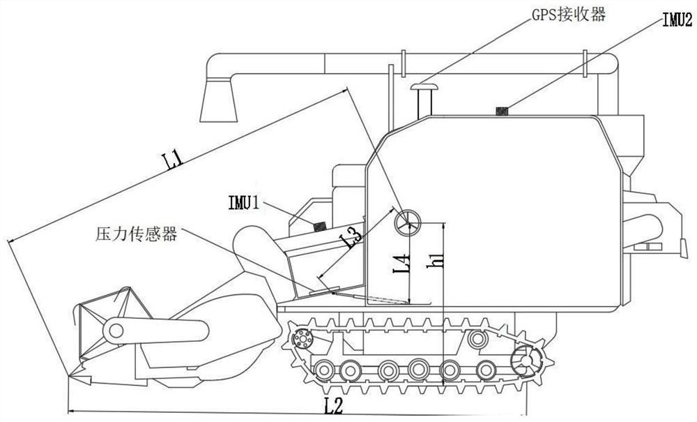
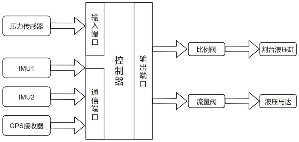
[0034] Such as figure 1 and figure 2 As shown, a combine harvester feeding control system includes an inertial measurement unit IMU1, an inertial measurement unit IMU2, a pressure sensor, a GPS receiver and a controller. Among them, IMU1 is installed at the outer shell of the inclined conveyor to detect the inclination of the header plane; IMU2 is installed above the granary and at the level of the vehicle body. The original data collected by the accelerometer and gyroscope of IMU2 are filtered by Kalman on the one hand. The horizontal attitude of the vehicle body is obtained, on the other hand, it is combined with the GPS data, and the precise forward speed of the vehicle body is obtained after Kalman filtering; the GPS receiver is installed in the open space above the...


PUM


Abstract

The present invention provides a system and method for regulating the feeding amount of a combine harvester. The regulating system includes IMU1, IMU2, a pressure sensor, a GPS receiver and a controller. The current feeding amount is within the rated range to maintain the header height and harvest The operating speed of the machine remains unchanged. When the feeding amount is not within the rated range, the IMU detects the posture of the vehicle body and the tilting conveyor of the header, and combines it to obtain the height of the header and the corresponding current hydraulic cylinder position at this height. By presetting the expected header Height, the obtained expected header hydraulic cylinder position, based on the error between the expected header hydraulic cylinder position and the current hydraulic cylinder position, and then through the controller to adjust the proportional valve to drive the hydraulic cylinder to expand and contract, to control the header height to stabilize at the expected position; based on the speed change , the controller controls the hydraulic motor speed by adjusting the flow valve, and then stabilizes the value of the vehicle speed after the change. The height and forward speed of the combined harvesting unit of the present invention maintain a stable feeding amount and high operating efficiency.

Description

technical field [0001] The invention belongs to the field of agricultural automation, and in particular relates to a system and a method for controlling the feeding amount of a combine harvester. Background technique [0002] The combine harvester is an important equipment in agricultural production. With the continuous expansion of actual operation scenarios and application scale, the degree of automation of harvesters has become an important research direction. Realize the stable control of the feeding amount of the harvester, which is conducive to reducing the loss rate of grains and improving work efficiency. [0003] There are many factors that affect the feeding amount of the harvester, and manual judgment requires rich prior knowledge. When operating a traditional harvester, the driver needs to pay attention to crop density, stubble height, and forward speed, etc., so that the harvester’s feeding amount Stable, such a working method will increase the labor intensity...

Claims


Application Information

Patent Timeline
Patent Type & Authority Patents(China)
IPC IPC(8): A01D41/127
CPCA01D41/1278
Inventor 魏新华刘青山张敏王爱臣
Owner JIANGSU UNIV
Why Eureka
Try Eureka