Saw blade type craniotomy device

A surgical device, saw blade technology, used in surgery, surgical instrument support, surgical saws, etc., can solve problems such as difficulty in automatic operation, impact on skull repair, and easy jamming of saw blades, achieve high torque output, and prevent contamination. , the effect of meeting the requirements of flexibility

Inactive Publication Date: 2021-05-11
CHONGQING YIXI BRAND PLANNING CO LTD
View PDF4 Cites 2 Cited by
  • Summary
  • Abstract
  • Description
  • Claims
  • Application Information

AI Technical Summary

Problems solved by technology

The current cutting connection mainly uses milling cutter slotting or saw blade to cut directly. The milling cutter slotting is very convenient and fast to use. The disadvantage is that the incision is too large, which will affect the later skull repair; Small, but it is easy to jam the saw blade, and the local heating of the saw blade is also a problem that needs to be solved, but the saw blade has high cutting efficiency and the later skull repair is very fast
Therefore, in practice, saw blade cutting is more beneficial to the later repair of patients, but it is difficult to realize automatic operation

Method used


Image

  • Saw blade type craniotomy device
  • Saw blade type craniotomy device
  • Saw blade type craniotomy device

Examples


Embodiment Construction

[0039] The following will clearly and completely describe the technical solutions in the embodiments of the present invention with reference to the drawings in the embodiments of the present invention.

[0040] In describing the present invention, it should be understood that the terms "upper", "lower", "front", "rear", "left", "right", "top", "bottom", "inner", " The orientation or positional relationship indicated by "outside", etc. is based on the orientation or positional relationship shown in the drawings, and is only for the convenience of describing the present invention and simplifying the description, rather than indicating or implying that the referred device or element must have a specific orientation, so as to Specific orientation configurations and operations, therefore, are not to be construed as limitations on the invention.

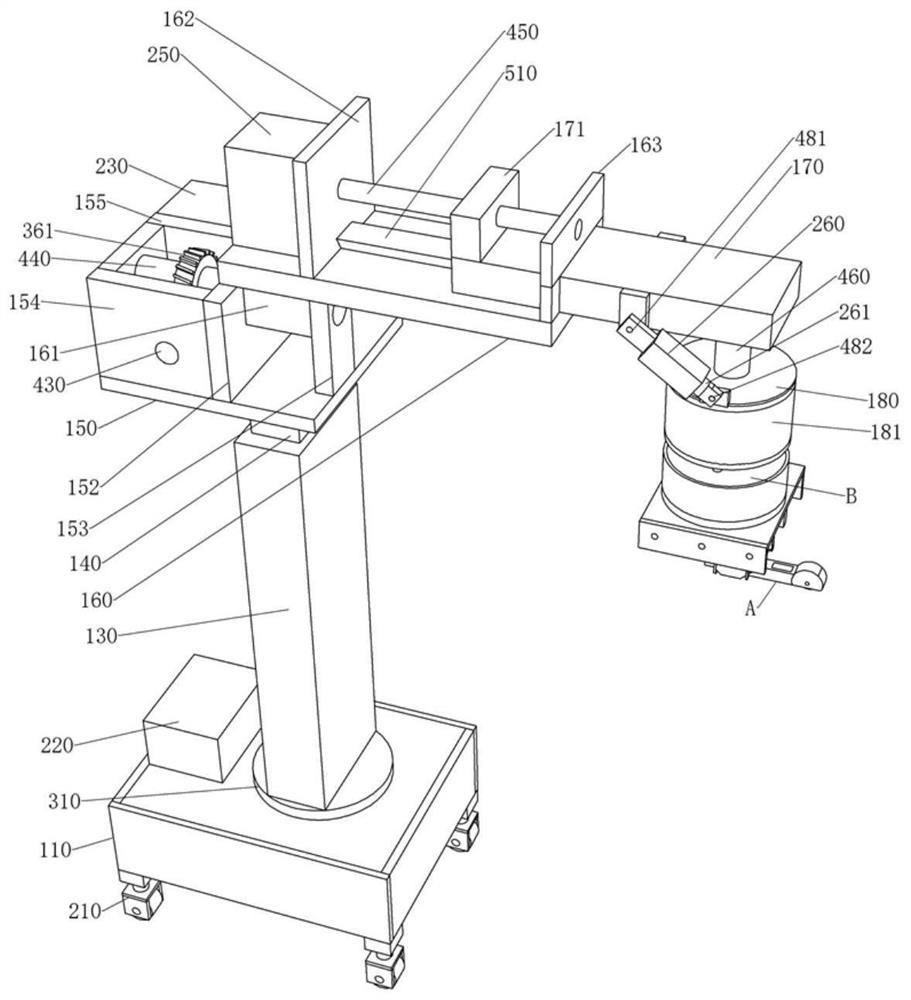
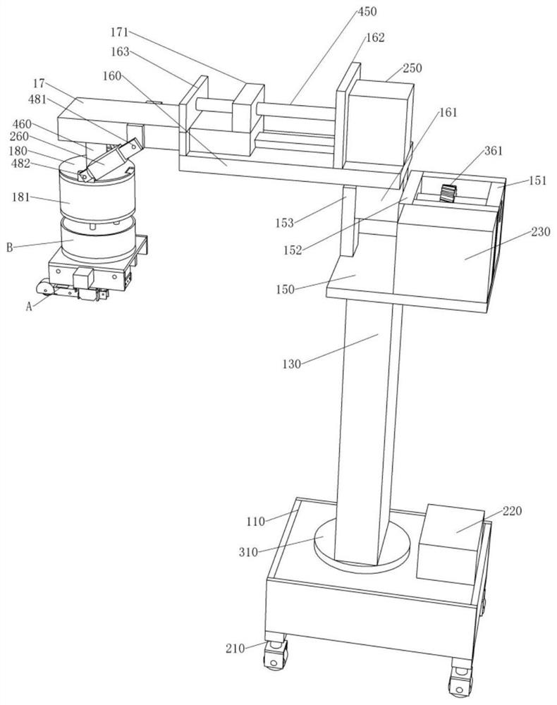
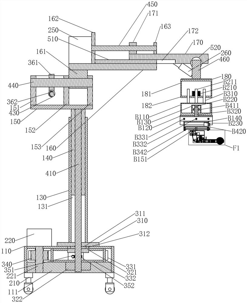
[0041] see Figure 1-Figure 32 , the saw blade type craniotomy device of the present embodiment includes a base 110, and a universal whe...


PUM


Abstract

The invention discloses a saw blade type craniotomy device. The saw blade type craniotomy device can directly cut open the skull through a saw blade and comprises a connecting frame, wherein a connecting cover is installed on the connecting frame, a connecting frame bottom plate is installed at the bottom of the connecting cover, a feed push rod motor is installed on the connecting frame bottom plate, a feed telescopic shaft is installed on the feed push rod motor, one end of the feed telescopic shaft penetrates through the connecting frame bottom plate and then is assembled with a first saw blade frame shell of a saw blade frame, the first saw blade frame shell is further assembled with one end of a feed guide shaft, and the other end of the feed guide shaft penetrates out of the connecting frame bottom plate and can be axially and slidably assembled with the connecting frame bottom plate; a rotating frame is installed in the first saw blade frame shell, the rotating frame and a rotating main shaft can be circumferentially and rotatably assembled, and the rotating main shaft penetrates through the first saw blade frame shell and then is assembled with a second saw blade frame shell; a lateral moving frame is installed on the second saw blade frame shell; and a saw blade base is installed on the lateral moving frame, a saw blade module is installed on the saw blade base, a saw blade is installed on the saw blade module, and the saw blade is used for cutting.

Description

technical field [0001] The invention relates to a craniotomy device, in particular to a saw blade type craniotomy device. Background technique [0002] Craniotomy is an operation in which the head is cut open to treat the brain. The operation steps are generally: 1. Cut the scalp; 2. Cut the skull; 3. Cut the dura mater; 4. Operate; 5. Suture the dura mater, skull and scalp one by one. [0003] At present, craniotomy is one of the commonly used brain surgeries, which usually takes more than 2-8 hours, and a lot of time is wasted on craniotomy. The incision of the skull is generally made by making three holes at the cutting site, and then cutting and connecting the three holes, so that the complete skull can be taken out. The current cutting connection mainly uses milling cutter slotting or saw blade to cut directly. The milling cutter slotting is very convenient and fast to use. The disadvantage is that the incision is too large, which will affect the later skull repair; ...

Claims


Application Information

Patent Timeline
Patent Type & Authority Applications(China)
IPC IPC(8): A61B17/14A61B17/15A61B90/00A61B90/50B08B15/04
CPCA61B17/15A61B2017/00017A61B2217/002A61B90/06A61B90/361A61B90/37A61B90/50A61B2090/061A61B17/147B08B15/04
Inventor 袁素
Owner CHONGQING YIXI BRAND PLANNING CO LTD
Why Eureka
Try Eureka